Download
1 / 17
170 likes | 270 Vues
The Avalanche Effect in Operation of Heavily Irradiated Si p-i-n Detectors. Vladimir Eremin , E. Verbitskaya, Ioffe Physical Technical Institute, Russia Z. Li Brookhaven National Laboratory, USA J. H ärkönen Helsinki Institute of Physics, Finland.

E N D
The Avalanche Effect in Operation of Heavily Irradiated Si p-i-n Detectors Vladimir Eremin, E. Verbitskaya, Ioffe Physical Technical Institute, Russia Z. Li Brookhaven National Laboratory, USA J. Härkönen Helsinki Institute of Physics, Finland RD 50 Workshop, Freiburg, 3 – 5 June, 2009
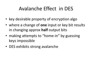
Motivation • The measured CCE at N-on P detectors reaches the value close to 100% or even higher. • For heavily irradiated detectors the operational voltage is high enough and even simple estimations of the electric field in the detector gives the range which fits to the avalanche multiplication phenomenon in silicon. • The topic is essential due to possible application of the detectors for LHC experiments upgrade. V. Eremin, RD 50 Workshop, Freiburg, 3 – 5 June, 2009
Multiplication effect in Silicon • Multiplication probability • (or ionization rate) for • electrons αn and holes αp at RT • αn(x)= exp[An – Bn/E(x)] An = 6.3e6, Bn = 1.23e6 • αp(x)= exp[Ap – Bp/E(x)] Ap = 1.74e6, Bp = 2.18e6 The ionization rates at RT for electrons and holes in silicon are very different. For E=2e5V/cm they are: an =210cm-1 and ap = 16cm-1. The basic equation for the gain calculation dn = dp =αn n(x)dx + αp p(x)dx V. Eremin, RD 50 Workshop, Freiburg, 3 – 5 June, 2009
Electric field evolution with fluence in PAD detectors (single peak model) The electric field in PAD N on P silicon detector d = 300um V = 500V g = 1.7e-2 cm-1 V. Eremin, RD 50 Workshop, Freiburg, 3 – 5 June, 2009
Depth profile of multiplication probability The N on P detector operates at: RT The detector thickness - 300um Fluence 1e16 neg/cm2 The trapping time: τe= τp= 2.5e-10 s, V. Eremin, RD 50 Workshop, Freiburg, 3 – 5 June, 2009
Fluence dependence of CCE Single peak model N on P d = 300um V = 1000V g = 1.7e-2 cm-1 Why calculation does not show monotonic dependence for CCE(F) ??? V. Eremin, RD 50 Workshop, Freiburg, 3 – 5 June, 2009
Voltage dependence of the CCE The detector operates at RT. The detector thickness is 300um. The trapping time: τe= τp= 2.5e-10 s, Collection electrons to the n+ strips Calculations made are based on trivial SP detector model. What is in a real strip detector ? V. Eremin, RD 50 Workshop, Freiburg, 3 – 5 June, 2009
The SPB (St. Petersburg) model for segmentation of avalanche detectors • The model has been developed at PTI in the mid of 90th for pixelization of avalanche photodiodes • The model considers geometry of the insulated segment and does not require the complicate packages for device simulation • In this study the model is extended for theheavily irradiated detector substrate by considering the electric field manipulation via the current injection. V. Eremin, RD 50 Workshop, Freiburg, 3 – 5 June, 2009
Electric field profile around the strip V. Eremin, RD 50 Workshop, Freiburg, 3 – 5 June, 2009
Electric field evolution with fluence in strip detectors Focusing electric field at the strip Vb = 500V Estr ~ 4.4Eblk ATLAS-SCT V. Eremin, RD 50 Workshop, Freiburg, 3 – 5 June, 2009
E(x) n+ strip Soft breakdown and hole injection with trapping X Current stabilization and electric field smoothing around strip The approach is based on explanation of the high break down voltage for the heavily irradiated P on N silicon detectors via the electric field suppression by the local current injection. (V. Eremin et. al., “Scanning Transient Current Study of the I-V Stabilization Phenomenon in Silicon Detectors Irradiated by Fast Neutrons”, NIM A, 388 (1977), 350.) The strip edge electric field will be suppressed as well V. Eremin, RD 50 Workshop, Freiburg, 3 – 5 June, 2009
The gain in adjacent strip area The Question: What is the value of electric field at the vicinity of strip which gives the CCE = 1 and how it depends on the width of injection modified layer. E(x) Δg(V) Es X Es ~ 2.1e5 V/cm at CCE ~ 1 V. Eremin, RD 50 Workshop, Freiburg, 3 – 5 June, 2009
Conclusions 1. The developed SPB model of charge multiplication in heavily irradiated detectors concedes two fundamental mechanisms which are well proofed and parameterized: • the avalanche multiplication in P-N junctions • the electric field controlled by current injection in the deep level dopped semiconductors. 2. The SPB model has only 2 free parameters: Δgand the electric field at the surface Es. 3. The key point for application of the SPB model is the electric field value in the detector base region and the potential sharing between the base and the depleted region adjacent to the strip side. 4. The SPB model shows that the charge multiplication effect can be only observed in the detectors with segmented N+ side. 5. The SPB model includes a “strong feed-back loop” via the current injection that explains the detector stable operation at the high voltage and the smoothed rise of the collected charge up to 100% of CCE. 6. The SPB model avoid the puzzle of the trapping time saturation at comparatively low concentration of trapping centers and allows to use the constant “β” parameter along the whole SLHC fluence range. V. Eremin, RD 50 Workshop, Freiburg, 3 – 5 June, 2009
Future plan • The SPB model will be applied for the electric field parameterization along the CCE(V) and CCE(F) experimental results. V. Eremin, RD 50 Workshop, Freiburg, 3 – 5 June, 2009
Thank you for your attention Acknowledgments This work was supported in part by: Federal agency of science and innovation of RF, RF President Grant # 2951.2008.2, Fundamental Program of Russian Academy of Sciences on collaboration with CERN. V. Eremin, RD 50 Workshop, Freiburg, 3 – 5 June, 2009