Download
1 / 50
1.17k likes | 2.28k Vues
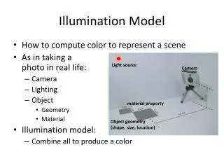
Illumination (Lighting). Outline. Light Source Basic Illumination Models Shading Methods Ray-Tracing Methods Radiosity Lighting Model Shadow. Introduction. Realistic displays of a scene Perspective projections of objects Applying lighting effects. Introduction (Contd.).

E N D
Outline • Light Source • Basic Illumination Models • Shading Methods • Ray-Tracing Methods • Radiosity Lighting Model • Shadow
Introduction • Realistic displays of a scene • Perspective projections of objects • Applying lighting effects
Introduction (Contd.) • Illumination model • Lighting model or Shading model • Calculate the intensity of light for a given point on the surface of an object • Surface-Rendering algorithm • Use the intensity of a given point to determine the light intensity for all projected pixel position in a polygon
(a) (b) Light Sources • Types of light source • light source (direct) • light reflector (indirect) • Two light emitter models • Point light source, see (b) • Distributed (Area) light source, see (a)
- Position - Orientation - Material - Light source - Viewer L N V Illumination Models • Concerning methods for calculating light intensity • Also called Lighting Models • An approximation for physical optical laws
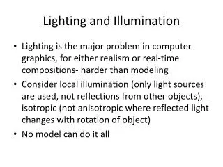
Types of illumination models • Local Illumination Models • Only considering the interchanges of the light sources • Global Illumination Models • Concerning the interchange of light between all surfaces • Ray-Tracing, Light as a particle • Radiosity, Light as a energy
D L T.L. S Phong Model • Phong in 1975 • The standard model that compromises between acceptable results and processing cost • Light source • A point light source • Light interactions with a solid: • incident light at a surface= light reflected +light scattered+ light absorbed+ light transmitted • Models reflected light as reflected light = ambient+ diffuse+ specular
Ambient Light • Equally on all surfaces from all directions. • Results from multiple reflections of light from the many surfaces in the environment • Our illumination equation becomes I = IaKa Ia : intensity of the ambient light( to be constant) • Ka :ambient-reflection coefficient ( 0 ~ 1) • depends on object’s material • be empirical convenience
N V L Diffuse Reflection • Dull and matte surfaces exhibit diffuse reflection • Equally bright from all viewing angles • The intensity on a given surface depends on the angle between the light's directionL and surface's normalN I= IaKa+ IpKdcos • Ip : Intensity of point light source • Kd : diffuse-reflection coefficient (0 ~ 1) • cos : max( cos , 0)
Total Diffuse Reflection • Assuming that N and L have been normalized, • I= IaKa+ IpKd(N dotL) Lis a constant if a point light source is at infinite (Called directional light source)
Kd, with Ka= 0 0.0 0.2 0.4 0.6 0.8 1.0 Visual Effects of Different Values of Kd
, where Diffuse Reflection - Further Discussions • Light-source attenuation • Colored lights and surfaces • Similar for IG and IB.
N N L L R V R Specular Reflection • Specular reflection can be observed on any shiny surface • The highlight presents the incident light n vary from 1 to ?00, it depends on surface material being simulated
H N L R V Specular Reflection • In Phong model does a good job of modeling specular reflection from plastic surfaces • Reduce the calculation of the reflection vector • where H= (L+ V)/| L+ V|
Visual Effects of Specular Reflections Ks 1.0 0.5 8 16 32 64 128 Shinness
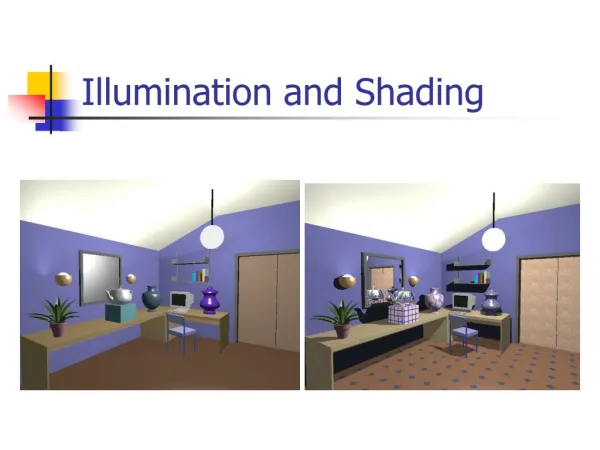
Visual Effects of Combined Reflections See Figure 10-23
L x cones flaps Improving the Point-Light-Source Model • Models the directionality of the lights • Warn 83 • Multiple light sources
Summary of the Phong Model • Light sources are assumed to be point sources • Light sources and viewer are located at infinity • Only the normal vector of a surface needs to be computed • The diffuse and specular terms are modeled as localcomponents • The color of the specularreflection is assumed to be that of the light source • ks is set to be a constant value independent of the surface color • The globalterm(ambient) is modeled as a constant • Drawback: • Gives the impression of colored plasticsurface
Illumination Models and Surface-Rendering Methods • Light Source • Basic Illumination Models • Shading Methods • Ray-Tracing Methods • Radiosity Lighting Model • Shadow
Normal Light View Shading Models for Polygons • Constant Shading
Constant-Intensity Shading • Also called flat shading • A single intensity is calculated for each polygon • Advantage • Quickly displayed with same intensity value • If a polyhedron is not an approximation of an object with a curved surface, flat shading provides an accurate rendering • Disadvantage • Not accurate rendering for an object
y I1 Ia Ib Ip I2 I3 Gouraud Shading • Also called Intensity-interpolation shading • Introduce Mach bands
Phong Shading • Normal-vectorInterpolation Shading • The rendered image is more acceptable • Increase the cost of shading
Gouraud Shaded Polygons with Diffuse and Specular Reflection
Viewing transformation Modeling transformation Modeling Rasterization (including shading) Clipping Display The Rendering Pipeline • For Z-buffer and Phong shading
Demo and Trace Demo Program • DiffuseDemo • Diffuse.fx -> DiffuseVS() • AmbientDiffuseDemo • AmbientDiffuse.fx -> AmbientDiffuseVS() • AmbientDiffuseSpecularDemo • ambientdiffusespec.fx -> AmbientDiffuseSpecVS()
A B B D A C D C Problems with Interpolated Shading • Polygonal silhouette • Improve by breaking the surface into a greater number of smaller polygons • Orientation dependence • Solved by decomposing polygons • Problems at shared vertices • Unrepresentative vertex normals A C B
Normal Vectors • To get the normal vector for a vertex • For a differentiable surface, use calculus to find • For not differentiable, use vertex normal averaging Averaging the four polygon face normals
R View N L Local R View T N L Global Global Illumination
Global Illumination Models • Recursive Ray-Tracing • Light regards as particle • Sharpening renderer, and view dependent • Radiosity • Light regards as energy • Smoothy renderer, and view independent
Illumination Models and Surface-Rendering Methods • Light Source • Basic Illumination Models • Shading Methods • Ray-Tracing Methods • Radiosity Lighting Model • Shadow
Shadows • Shadow algorithms determine which surfaces can be seen from light source. • In multiple light sources, we have problems. • umbra and penumbra. • Illumination equation involving shadows
Remarks • Light Source • Basic Illumination Models • Shading Methods • Ray-Tracing Methods • Radiosity Lighting Model • Shadow