Download
1 / 34
360 likes | 546 Vues
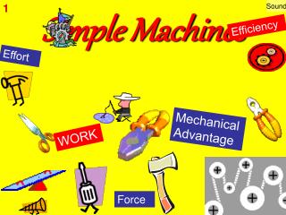
The 6 Simple Machines. Screw. Wedge. Inclined Plane. Pulley. Wheel and Axle. Lever. Definitions:. Energy:. Ability to do work. Work=. Force x Distance. Force:. A Push or a Pull. Inclined Plane. Inclined Plane.

E N D
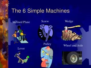
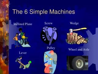
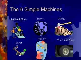
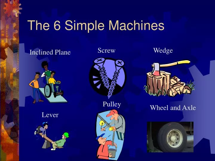
The 6 Simple Machines Screw Wedge Inclined Plane Pulley Wheel and Axle Lever
Definitions: Energy: Ability to do work Work= Force x Distance Force: A Push or a Pull
Inclined Plane • The Egyptians used simple machines to build the pyramids. One method was to build a very long incline out of dirt that rose upward to the top of the pyramid very gently.
Inclined Plane • The blocks of stone were placed on large logs (another type of simple machine - the wheel and axle) and pushed slowly up the long, gentle inclined plane to the top of the pyramid.
Inclined Planes • An inclined plane is a flat surface that is higher on one end • Inclined planes make the work of moving things easier
Work input and output • Work input is the amount of work done on a machine. • Input force x input distance • Work output is the amount of work done by a machine. • Output force x output distance Wout = Win Fout x Dout = Fin x Din 10 N x 3 m = 2 N x 15 m 15 m Din Dout 3 m Fin 10 N
Inclined Plane -Mechanical Advantage • The mechanical advantage of an inclined plane is equal to the length of the slope divided by the height of the inclined plane.
Inclined Plane -Mechanical Advantage • While the inclined plane produces a mechanical advantage, it does so by increasing the distance through which the force must move.
Screw The mechanical advantage of an screw can be calculated by dividing the circumference by the pitch of the screw. Pitch equals 1/ number of turns per inch.
Wedges • Two inclined planes joined back to back. • Wedges are used to split things.
Wedge – Mechanical Advantage • The mechanical advantage of a wedge can be found by • dividing the length of either slope (S) by the thickness (T) of the big end. S T
Wedge – Mechanical Advantage As an example, assume that the length of the slope is 10 cm and the thickness is 4 cm. The mechanical advantage is equal to 10/4 or 2.5. As with the inclined plane, the mechanical advantage gained by using a wedge requires a corresponding increase in distance. S T
First Class Lever Fulcrum is between EF (effort) and RF (load)Effort moves farther than Resistance.Multiplies EF and changes its direction
First Class Lever The mechanical advantage of a lever is the ratio of the length of the lever on the applied force side of the fulcrum to the length of the lever on the resistance force side of the fulcrum.
First Class Lever . • Common examples of first-class levers include crowbars, scissors, pliers, tin snips and seesaws.
Second ClassLever RF (load) is between fulcrum and EF Effort moves farther than Resistance.Multiplies EF, but does not change its direction
Second ClassLever The mechanical advantage of a lever is the ratio of the distance from the applied force to the fulcrum to the distance from the resistance force to the fulcrum.
Second Class Lever • Examples of second-class levers include nut crackers, wheel barrows, doors, and bottle openers.
Third Class Lever EF is between fulcrum and RF (load) Does not multiply force Resistance moves farther than Effort.Multiplies the distance the effort force travels
Third Class Lever The mechanical advantage of a lever is the ratio of the distance from the applied force to the fulcrum to the distance of the resistance force to the fulcrum
Third Class Lever • Examples of third-class levers include tweezers, arm hammers, and shovels.
Pulleys • Pulley are wheels and axles with a groove around the outside • A pulley needs a rope, chain or belt around the groove to make it do work
Diagrams of Pulleys Fixed pulley: A fixed pulley changes the direction of a force; however, it does not create a mechanical advantage. Movable Pulley: The mechanical advantage of a moveable pulley is equal to the number of ropes that support the moveable pulley.
COMBINED PULLEY • The effort needed to lift the load is less than half the weight of the load. • The main disadvantage is it travels a very long distance.
WHEEL AND AXEL • The axle is stuck rigidly to a large wheel. Fan blades are attached to the wheel. When the axel turns, the fan blades spin.
Wheel and Axel • The mechanical advantage of a wheel and axle is the ratio of the radius of the wheel to the radius of the axle. • In the wheel and axle illustrated above, the radius of the wheel is five times larger than the radius of the axle. Therefore, the mechanical advantage is 5:1 or 5. 1 5
Wheel and Axel • The wheel and axle can also increase speed by applying the input force to the axle rather than a wheel. This increase is computed like mechanical advantage. This combination would increase the speed 5 times. 5 1
GEARS-Wheel and Axel • Each gear in a series reverses the direction of rotation of the previous gear. The smaller gear will always turn faster than the larger gear.
Rube Goldberg Machines • Rube Goldberg machines are examples of complex machines. • All complex machines are made up of combinations of simple machines.
Rube Goldberg Machines • Rube Goldberg machines are usually a complicated combination of simple machines. • By studying the components of Rube Goldberg machines, we learn more about simple machines
Safety Device for Walking on Icy Pavements When you slip on ice, your foot kicks paddle (A), lowering finger (B), snapping turtle (C) extends neck to bite finger, opening ice tongs (D) and dropping pillow (E), thus allowing you to fall on something soft.