Download
1 / 36
370 likes | 1.06k Vues
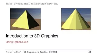
3D Graphics Introduction Part 2. CIS 488/588 Bruce R. Maxim UM-Dearborn. 3D Data Structures. Triangles Pros: very good, very fast Cons: need lots of them Quadrilaterals Pros: good, fast Cons: non-coplanar Polygons Pros: easy to model with them Cons: hard to draw, hard to clip.

E N D
3D Graphics IntroductionPart 2 CIS 488/588 Bruce R. Maxim UM-Dearborn
3D Data Structures • Triangles • Pros: very good, very fast • Cons: need lots of them • Quadrilaterals • Pros: good, fast • Cons: non-coplanar • Polygons • Pros: easy to model with them • Cons: hard to draw, hard to clip
Defining Polygons - 1 • Suppose we decide to model all polygons using triangles • Assume the rasterizer will clip triangles as needed as they are drawn (avoiding the use of 3D clipping in this chapter) • To avoid redundant listing of vertex information it is wise to use a vertex list to define 3D shapes
Defining Polygons – 2 • For a cube the vertices might be POINT3D vertex_list[NUM_VERTICES]; vertex_list[0] = {x0, y0, z0}; … vertex_list[7] = {x7, y7, z7}; struct typedef POLY_EX_TYP_2 { POINT3D_PTR vlist: int vertices[3]; } POLY_EX_2, *POLY_EX_2_PTR; POLY_EX_2 face1 = {vertex_list, 0, 1, 2};
Defining Polygons – 3 • One advantage of the vertex list method is that you avoid vertex drift that results when several copies of the same vertex are transformed independently (known as geometry cracking – as seen in Tomb Raider) • Sometimes you need to separate the polygons and vertex lists (esp. if you only need to render 1 of thousands of triangles in a surface)
Defining Polygons – 4 • Another problem comes with clipping the vertex list without examining the polygons (you end up clipping any polygon the shares the clipped vertex) • To avoid this, you might need to adopt a hybrid approach that involves defining and transforming vertex lists and also convert them to single polygons when necessary
Defining Polygons - 5 // a polygon based on an external vertex list typedef struct POLY4DV1_TYP { int state; // state information int attr; // physical attributes of polygon int color; // color of polygon POINT4D_PTR vlist; // the vertex list itself int vert[3]; // the indices into the vertex list } POLY4DV1, *POLY4DV1_PTR;
Defining Polygons - 6 // a self contained polygon used for the render list typedef struct POLYF4DV1_TYP { int state; // state information int attr; // physical attributes of polygon int color; // color of polygon POINT4D vlist[3]; // vertices of this triangle POINT4D tvlist[3]; // vertices after transformation if needed POLYF4DV1_TYP *next; // pointer to next polygon in link list POLYF4DV1_TYP *prev; // pointer to previous polygon in LL } POLYF4DV1, *POLYF4DV1_PTR;
Defining Objects - 1 • Object contains everything needed for the 3D pipeline even transformed coordinates • Static arrays are used (they waste storage but avoid allocation and deallocation of storage) • Limited to 64 vertices and 128 polygons • Radius fields are used to assist in culling • “dir” is used to track rotations as local coordinates are overwritten
Defining Objects - 2 typedef struct OBJECT4DV1_TYP { int id; // numeric id of this object char name[64]; // ASCII name of object just for kicks int state; // state of object int attr; // attributes of object float avg_radius; // average radius of object used for //collision detection float max_radius; // maximum radius of object POINT4D world_pos; // position of object in world VECTOR4D dir; // rotation angles of object in local // cords or unit direction vector user // defined???
Defining Objects - 3 VECTOR4D ux,uy,uz; // local axes to track full orientation // this is updated automatically during // rotation calls int num_vertices; // number of vertices of this object POINT4D vlist_local[OBJECT4DV1_MAX_VERTICES]; // local vertices POINT4D vlist_trans[OBJECT4DV1_MAX_VERTICES]; // transformed ver int num_polys; // number of polygons in object mesh POLY4DV1 plist[OBJECT4DV1_MAX_POLYS]; // array of polygons } OBJECT4DV1, *OBJECT4DV1_PTR;
Representing Worlds • Can’t just throw dozens or objects made up of hundreds of polygons into the graphics pipeline without taking a performance hit • In reality only a small portion of the game world will be visible from any given viewpoint • Terrain does not change much so its images could be left in world coordinates avoiding a local world transformation • More advanced techniques are discussed in later chapters
3D Modeling Tools • Calagari trueSpace • Maya • LightWave • 3D Studio Max • Blender • Moray coupled with a ray tracer like Persistence of Vision (POV)
PLG File Format - 1 • There are some modelers that produce PLG files and utilities to convert DXF to PLG files • Format • Header line object_name num_vertices num_polygons • Vertex list (0 to n in x-y-z order) x_coord y_coord z_coord • Polygon list surface_description n v1 v2 v3 … vn
PLG File Format - 2 • Surface description code – 16 bits (can be either hex or decimal) H15 – 1 means interpret as bottom 14 bits as surface map index otherwise use table interpret to S13S12 R14 – reserved should be 0 S13S12 – 00 solid shaded, 01 flat shaded, 10 metallic, 11 transparent C11C8 – one of 16 color hues B7B0 – brightness of color
NFF File Format • Neutral file format (virtual reality games) • Supports • Simple perspective frustrum • Background color descriptions • Positional light source description • Surface properties description • Polygon, polygon patch, cylinder/cone, and sphere descriptions (in vertex format)
NFF Example v // viewport location from 0 2.0 2.0 at 0 0 0 up 0 1 0 angle 40 hither 1 resolution 512 512 l 0 5 0 // positional lights l 0 2.0 2.0 f 0.000000 0.000000 0.000000 1 0 0 0 0 // fill light p 3 // polygon format 1.000000 -1.000000 -1.000000 -1.000000 -1.000000 -1.000000 -1.000000 -1.000000 -1.000000
DXF File Format • Binary and ACSCII versions originally supported by AutoCAD • Format • Header Section (general model info) • Tables Section (definitions of named objects) • Blocks Section (lists entities for each block) • Entities Section (contains actual model entities) • End of File Marker
Other File Formats • 3DS • Binary format produced by 3D Studio Max also has an ASCII version • Largely a file header followed by vertex and face information • COB • Produced by Calagari trueSpace • Vertex based format similar to 3DS • .X • Microsoft Direct X format, contains everything Direct 3D handles importing
3D Mesh Translation • Simply adjust its position vector • To move an object by t=<tx, ty, tz> object.world_pos.x = Object.world_pos.x + t.x; object.world_pos.y = Object.world_pos.y + t.y; object.world_pos.z = Object.world_pos.z + t.z; • To move in elliptical path parallel to x-z plane using absolute coordinates x_pos = a * cos(angle); y_pos = altitude; z_pos = b * sin(angle);
3D Mesh Rotation • Need to track orientation relative to the axis (to avoid problems like gimbal lock) • Should rotate an object’s local coordinates placing (0,0,0) at the object center • Need an orientation vector “dir” the is aligned pointing down the z+ axis • “dir” is update any time the object is rotated to keep track of its current orientation
3D Mesh Morphing • Scaling and shearing done in real-time to make something look alive (e.g. breathing) int up_down = 1; float scale = 1; while(1) { if (up_down == 1) { Scale_Object(&object, 1.05); scale = scale * 1.05; }
3D Mesh Morphing else { Scale_Object(&object, .95); scale = scale * .95; } if ((scale < .75) || (scale > 1.25)) up_down = -up_down; } • Note eventually errors (drift) will start creeping into the images and we will have to refer to the original copies of each mesh and apply the transformations to these instead
Types of 3D Engines • Space Engines (Star Wars:X-Wing) • Terrain Engines (Tread Marks) • FPS Indoor Engines (Unreal) • Ray Casters (Wolfenstein) • Voxel Engines (Medical Imaging) • Hybrid Engines (ray casting or polygons for worlds and sprites for objects)
Painter’s Algorithm • Basic idea • Sort surfaces and then draw so looks right. • If all surface are parallel to view plane, sort based on distance to viewer, and draw from back to front. • Worst-case is O(n^2) • Otherwise, have five tests applied to each pair to sort.
Test 1: X overlap • If the x extents of two polygons do not overlap, then order doesn’t matter and go to next pair. • If x extents overlap, goto test 2. +y +x
Test 2: Y Overlap • If the y extents of two polygons do not overlap, then order doesn’t matter. • If y extents overlap, goto test 3. +y +x
Tests 3 & 4 • Extend polygons to be a cutting plane • If a polygon can be contained within the cutting plane of the other, that polygon should be drawn first. • If neither can be contained, go to step 5.
Tests 3 & 4 View direction Polygon 1 is completely on one side of the two planes “cut” by polygon 2. Polygon 2 +z Polygon 1 +x
Test 5 • Only needs to be consider if have concave polygons.
How to make it easier • Use convex objects • Avoid long objects (like walls) that can overlap each other in multiple dimensions • Avoid intersecting objects and polygons
Z-buffer • Z-buffer holds the z-coordinate of every pixel • Initialize all values to maximum depth • Compute the z value of every point of every non-back facing polygon • Not too hard if all polygons are triangles or rectangles • Do this during the filling of the triangles • If z of point < z in Z-buffer • save the color of the current point and update Z-buffer • otherwise throw away point and move on
Ray Tracing • Image space technique that mimics physical processing of light • Extremely computationally intensive • Hidden surface removal • Transparency • Reflections • Refraction • Ambient lighting • Point source lighting • Shadows