Download
1 / 15
150 likes | 259 Vues
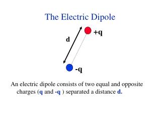
The LT Dipole. July 8 th , 2014. Motivation. Combine expertise of LBNL & TAMU to overcome common obstacles and reach higher fields with regular milestones Modular approach LT1: 13T Nb 3 Sn open-aperture (9x5 cm 2 ) LT2: 15T, LT1 + a racetrack of BSCCO-2212

E N D
The LT Dipole July 8th, 2014
Motivation • Combine expertise of LBNL & TAMU to overcome common obstacles and reach higher fields with regular milestones • Modular approach • LT1: 13T Nb3Sn open-aperture (9x5 cm2) • LT2: 15T, LT1 + a racetrack of BSCCO-2212 • LT3: 19T, LT2 + a flared winding of BSCCO-2212 • Stress management and continuous support of reacted cable to avoid damage losses
Magnetics for LT3 Stress management structure
Before pancake winding Window for quench heaters and voltage taps Add pic of just mandrel
Mandrel ‘heart’ Common design allows part reuse Thin-skin slots into place Magnetic cutout also serves as a slot
Pre-structure for flare These pieces provide supported form, and allow safe removal of flare • 873mm bending radius, 10° arc (same as HD3)
Flared winding and structure Window for quench heaters and voltage taps Pins for flare?
Remove mandrel ‘heart’ and install spanner plates Aperture now cleared in end pieces • Continuous support of Nb3Sn mitigates assembly damage
Assembling two halves Common wall pushes out plates through thick-skin • Continuous support of Nb3Sn mitigates assembly damage
Bladder/key magnet assembly • Similar to HD2/HD3, yoke is keyed against shell, then coil package is inserted and keyed