Download
1 / 52
641 likes | 1.11k Vues
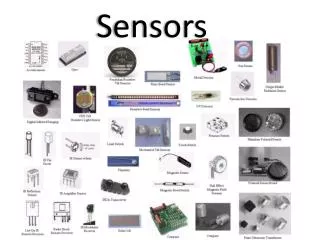
Sensors. Efrain Teran Carol Young Brian O’Saben. Optical Encoders. Efrain Teran. What are Optical Encoders ?. An Optical R otary Encoder is an electro-mechanical device that converts the angular position of a shaft to a digital code. What are they used for?.

E N D
Sensors Efrain Teran Carol Young Brian O’Saben
Optical Encoders Efrain Teran
What are Optical Encoders ? An Optical Rotary Encoder is an electro-mechanical device that converts the angular position of a shaft to a digital code. What are they used for? • Provide information on angular position, speed, and direction. • The information is used for system control (e.g. motor velocity feedback control). • It is the most popular type of encoder.
How do they work? • Use light and photo detectors to produce a digital code • As the encoder shaft rotates, output signals are produced proportional to the angle of rotation. • The signal may be a square wave (for an incremental encoder) or an absolute measure of position (for an absolute encoder).
Optical Encoder parts Light source: produces the light that will “trigger” the photodetectors during motion. Usually LEDs or IR LEDs Photodetector: electronic sensor that reacts to light. Usually a phototransistor or photodiode. Code disk: has one or more tracks with slits (windows) to allow light to pass through. Mask: collimates the beams of light
Optical Encoder parts Shaft: mechanically attached to the system we want to measure; usually a motor. Housing: protection from the environment. Electronic board: filters signal into square wave used by microcontroller.
Types of Optical Encoders Incremental Optical Encoders: • Single channel • Dual channel • Dual channel with Z index Absolute Optical Encoders
Incremental Encoders • Generate a series of pulses as the shaft moves and provide relative position information. • They are typically simpler and cheaper than absolute encoders. • Need external processing of signals. TYPES
Incremental Optical Encoder: Single channel • Has only one output channel for encoding information. • Used in unidirectional systems or where you don’t need to know direction. Voltage Lo Hi Lo Hi Lo Binary 0 1 0 1 0
Incremental Optical Encoder: Dual channel • The output has two lines of pulses (“A” and “B” channel) • They are 90° offset in order to determine rotation direction. • This phasing between the two signals is called quadrature. Channel A Lo Hi Hi Lo Repetitive sequence Channel B Lo Lo Hi Hi
Incremental Optical Encoder: Dual channel with Z index • Some quadrature encoders include a third channel (Z or Index) • It supplies a single pulse per revolution used for precise determination of a reference position. • Need to do “homing” for it to work. Doesn’t hold after power down. Z
Absolute Encoders • Provides a unique digital output for each shaft position • The code disk has many tracks. The number determines resolution. • Upon a loss of power it keeps the correct position value. • Uses binary or “grey” code.
Absolute encoders: Binary vs. Gray code 010 001 011 000 100 111 101 110 Transition possible results: 011 - 010 - 001 - 011- 111 - 100
Absolute encoders: Binary vs. Gray code 011 001 010 000 110 100 111 101 Transition possible results: 010 - 110
Encoder Resolution Absolute Optical Encoder • Resolution can be given in number of bits or degrees • Depends on the number of tracks on the code disk. Each track requires an output signal, also known as an “encoder bit”. • Resolution = 360°/(2N) • N= number of encoder bits (number of tracks) Example: An absolute encoder has 8 tracks on the disc. What is its angular resolution in degrees? • Resolution = 360°/(2N) = 360°/(28) = 1.4°
Encoder Resolution Incremental Optical Encoder • Resolution essentially depends on the number of windows on the code disk • Resolution = 360/N • N = number of windows on code disk Example: What number of windows are needed on the code disk of an incremental optical encoder to measure displacements of 1.5°? • Resolution=360° /N =1.5 °→ N = 240 windows • BUT, we can increase resolution by using channels A and B
Encoder Resolution Incremental Optical Encoder • We may count rising and falling edges in both channel’s signals Today’s standard • X4 Resolution= 360/4N • N = number of windows (slits or lines) on the code disk
(SabriCentinkunt, page 236) Example: Consider an incremental encoder that produces 2500-pulses/revolution. Assume that the photo detectors in the decoder circuit can handle signals up to 1 MHz frequency. Determine the maximum shaft speed (RPM) the encoder and decoder circuit can handle.
Applications Incremental Single channel Incremental Dual channel Incremental with Z index Absolute Encoder
REFERENCES: Mechatronics, SabriCetinkunt, Wiley, 2007. Section 6.4.3 http://en.wikipedia.org/wiki/Rotary_encoder http://www.ab.com/en/epub/catalogs/12772/6543185/12041221/12041235/Incremental-Versus-Absolute-Encoders.html http://www.ni.com/white-paper/7109/en/ http://www.digikey.com/PTM/IndividualPTM.page?site=us&lang=en&ptm=2420
Laser Interferometer Carol Young
What is a Laser Interferometer ? • Laser- single frequency light wave • Interferometry- Family of techniques where waves are super imposed in order to extract information about the waves • Uses the interference patterns from lasers to produce high precision measurements
Physics BackgroundWaves • Light is an Electrometric wave and therefore has wave properties. http://en.wikipedia.org/wiki/File:Light-wave.svg
Physics BackgroundDiffraction and Interference • Diffraction • Light spreads after passing a narrow point • Interference • superposition of two waves to form new wave with different amplitude • Constructive or Destructive http://en.wikipedia.org/wiki/File:Doubleslit3Dspectrum.gif
Types of Laser Interferometers • Homodyne • Homo (same) + dyne (power) • Uses a single frequency to obtain measurements • Heterodyne • Hetero (different) + dyne (power) • Uses two different (but close) frequencies to obtain measurements.
Homodyne Interferometer(Michelson) Mirror Reference Laser Mirror Moveable (Sample) Beam Splitter Screen
Homodyne InterferometerAnalysis • λ is the wavelength of the light • Lref is the distance to the reference mirror • L is the distance to the moveable mirror • n is the number of fringes Photograph of the interference fringes produced by a Michelson interferometer.
Homodyne InterferometerUses • Absolute distance • Optical testing • Refractive index • Angles • Flatness • Straightness • Speed • Vibrations
Physics BackgroundDoppler Effect • Point creating a wave and movement • Wave ahead of point has higher frequency • Wave behind point has lower frequency • Frequency change corresponds to velocity http://en.wikipedia.org/wiki/File:Dopplereffectsourcemovingrightatmach0.7.gif
Physics BackgroundBeat Frequency • Rate of constructive and destructive interference
Heterodyne Interferometer • Produces two close but not equal frequencies (Creating a Beat Frequency) • Doppler effect from moving reflector shifts the frequency proportional to the velocity
Heterodyne / HomodyneInterferometerComparison • Comparing with a Homodyne Interferometer • Can determine movement direction (but limited range) • More useful when direction of movement is important
Heterodyne / HomodyneInterferometer Comparison • Homodyne • Smooth surfaces only • Heterodyne • Can be used for • Distance to rough surfaces • Surface roughness measurements
Xiaoyu Ding Resolution • XL-80 Laser Measurement System
References • http://www.aerotech.com/products/engref/intexe.html • http://www.renishaw.com/en/interferometry-explained--7854 • http://en.wikipedia.org/wiki/Michelson_interferometer • http://en.wikipedia.org/wiki/Interferometry • http://en.wikipedia.org/wiki/Doppler_effect • www.ljmu.ac.uk/GERI/GERI_Docs/interferometry_presentation(1).ppt • http://www.olympus-controls.com/documents/GEN-NEW-0117.pdf • http://www.lambdasys.com/product/LEOI-20.htm • http://www.intechopen.com/books/advances-in-solid-state-lasers-development-and-applications/precision-dimensional-metrology-based-on-a-femtosecond-pulse-laser • http://en.wikipedia.org/wiki/Fringe_shift • http://www.gitam.edu/eresource/Engg_Phys/semester_1/optics/intro_polari.htm • A. F. Fercher, H. Z. Hu, and U. Vry, “Rough surface interferometry with a two-wavelength heterodyne speckle interferometer”, Applied Optics
Linear Variable Differential Transformer (LVDT) Brian O’Saben
Outline • What is a LVDT? • How LVDTs Works • LVDT Properties • LVDT Support Electronics • Types of LVDTs • LVDT Applications
What is a LVDT? • Linear variable differential transformer • Electromechanical transducer measuring linear displacement
What is a LVDT? • Primary coil • Energized with constant A/C • Two identical secondary coils • Symmetrically distributed • Connected in opposition • Ferromagnetic core
How LVDT works • If core is centered between S1 and S2 • Equal flux from each secondary coil • Voltage E1 = E2
How LVDT works • If core is closer to S1 • Greater flux at S1 • Voltage E1 increases, Voltage E2 decreases • Eout=E1 – E2
How LVDT works • If core is closer to S2 • Greater flux at S2 • Voltage E2 increases, Voltage E1 decreases • Eout=E2 – E1
LVDT properties • Friction-free operation • Unlimited mechanical life • Infinite resolution • Separable coil and core • Environmentally robust • Fast dynamic response • Absolute output
LVDT support electronics • LVDT signal conditioning equipment • Supply excitation power for the LVDT • Typically 3 Vrms at 3 kHz • Convert low level A/C output to high level DC signals • Gives directional information based on phase shift
Types of LVDTs • DC LVDT • Signal conditioning equipment built in • Pre-calibrated analog and/or digital output • Lower overall system cost • AC LVDT • Wide operating environments • Shock and vibration • Temperature • Smaller package size
Types of LVDTs • Separate core • Core is completely separable from the transducer body • Well-suited for short-range (1 to 50mm), high speed applications (high-frequency vibration) • Guided core • Core is restrained and guided by a low-friction assembly • Both static and dynamic applications • working range (up to 500mm) • Spring-loaded • Core is restrained and guided by a low-friction assembly • Internal spring to continuously push the core to its fullest possible extension • Best suited for static or slow-moving applications • Lower range than guided core(10 to 70mm)
LVDT applications • Industrial gaging systems • Electronic dial indicators • Weighing systems • Crankshaft balancer • Final product inspection (checking dimensions) • Octane analyzer (provides displacement feedback for Waukesha engine) • Valve position sensing