Download
1 / 2
250 likes | 1.25k Vues
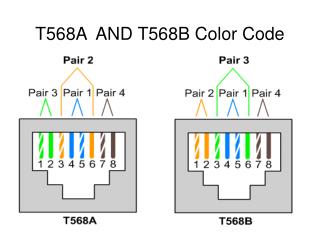
Telephone color code. Cat3. Cat5. RING TIP. RING TIP. L1. L1. RING TIP. RING TIP. L2. L2. L2. RING TIP. L3. L1. L4. RING TIP. L2. L1. Back-side of Telephone wall plate. SILVER SATIN. Telephone Install Concept for Line 1. 1. 2. 4.

E N D
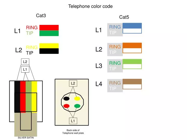
Telephone color code Cat3 Cat5 RING TIP RING TIP L1 L1 RING TIP RING TIP L2 L2 L2 RING TIP L3 L1 L4 RING TIP L2 L1 Back-side of Telephone wall plate SILVER SATIN
Telephone Install Concept for Line 1 1 2 4 To help identify your alarm line it is usually connected to a phone biscuit or on the bottom right of panel to screws labeled ring/tip inside the alarm box. Sometimes this has not been connected in alarm box just splice your feed from the common block to the back-feed. Run or use pre-wire for your dedicated line to your common block(You can use any color for this but these are the most common ones).With prewired there are usually two ways it has been done loop or to one place like a splitter location. You must tone it out either way. Connect your dedicated line in the common block to the bottom right tab labeled MTA (The blue tab) If there is no alarm connect the line to the tab labeled S-IN(Theorangetabon the bottom left) and skip steps 3-5 and go to step 6. 3 Identify your alarm feed outside at common block.(If you look in the alarm box it will be the only phone wire in the box).Connect it to the tab labeled S-OUT(Theorange tab bottom right).Occasionally you will see green/green-white spliced together in the same piece of cat5 don’t cut it that will set off the alarm. 3.S-OUT or or 2.MTA 5.S-IN DEDICATED LINE ALARM LINE The most common back-feed from the alarm are these colors. Place these in the tab labeled S-IN in the common block (The orange tab on the bottom left). ALARM BOX 5 or BACK FEED Now connect all your phone lines to the red/green tabs on the left inside the common block (usually the blue/white and red/green lines) Make sure to connect line 2 on right side (yellow/black tabs). 7 6 You should be done! Now go check to see if you have dial-tone. or HOME PHONE LINES If your line1 is blinking on the MTA you probably have a short. The best way is to disconnect each line from the common block/splice locations one by one until it stops the blinking. Then reconnect all the lines but the one that stopped the blinking. Go around and check every line with your test phone then inform the customer which jack doesn’t work and what it may cost to get it fixed. The reason to connect alarms this way is for line seizure .For example if the alarm is tripped while someone is using the phone. The alarm will disconnect that persons call and use the line to call out to the alarm company. It is required that every alarm be connected this way. A SLOTH N DOWNS BOY IDEA