Download
1 / 25
250 likes | 358 Vues
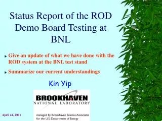
A summary of system tests at BNL related to the ROD. From a user point of view : Description of the system of the test stand at BNL Various capabilities of our test stand, the works done and the experience Data integrity, continuity and noise up to 100 kHz. presented by Kin Yip. Host 1.

E N D
A summary of system tests at BNL related to the ROD From a user point of view : Description of the system of the test stand at BNL Various capabilities of our test stand, the works done and the experience Data integrity, continuity and noise up to 100 kHz presented by Kin Yip
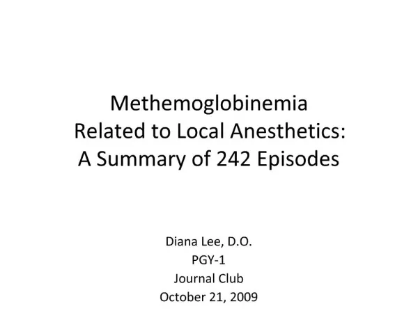
Host 1 ROD PTG TTC Control PU OC SDRAM trigger FE Crate TSA Board Calib. board trigger veto FEB ~VME Host 2 Signal from a pulser (triggered by TTC) Data (through optical link) • “Host 2” — single board in the same crate as the ROD — is a diskless node booted from “Host 1” through the network
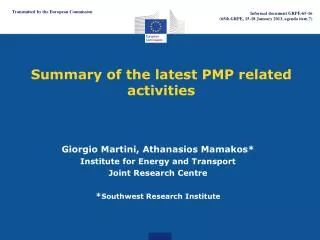
CPU board hidden inside
Brief system descriptions • Front-End Crate (~final) : FEB (Nevis, U. Columbia), calibration board (LAPP, Annecy), trigger summing analyzer (U. Pittsburg) • TTC (just like the testbeam, Saclay) • PTG (Pulse Trigger Generator) etc., “home-made" by BNL (H. Chen) • ROD (Read-Out Driver) Demo Board: • Motherboard from U. Geneva (input up to 2 FEB) • PU (TI 6202) from Nevis, U. Columbia (64 input each) • Optical Glink Rx/Tx cards from SMU, Texas • Transition module from KTH, Stockholm • Softwares and firmwares in concern : • DSP codes originally and mostly from Nevis (sometimes I modify) • Input FPGA firmware from Nevis (5 samples vs 32 samples) • Output Controller firmware from U. Geneva (quite a few upgrades) • ROD system software, U. Geneva and BNL
signal delay FEB ROD 10 s Data Relative Trigger and Data timing Triggers E, T, 2 calculation takes less than time than passing the entire FEB event (drawn not to scale )
1 Nothing is trivial • With some initial struggles with the VME crate, ROD demo board, and other “accessories”, • we first managed: • data in host PC thru’ VME ROD E, T, 2 VME to PC • then we took data from the FEB and we immediately realized that it is useful to program the PU to just copy all the data bits from the FEB, which is useful for debugging and detailed calibration analysis this becomes the most popular running mode • We first read 5 sample FEB data (nominal) • For calibration and other purposes, we have also taken 32 sample data. This requires changing the DSP codes and the FPGA firmware in the PU. • There have been a lot of detailed data debugging to make the whole scheme work
2 Nothing is trivial • One typical mode of running : • Trigger FEB PU/OC SDRAM on ROD motherboard • When the SDRAM is full, “BUSY” is raised veto trigger • Transfer all data in SDRAM host PC through VME (~3 seconds) • Transfer data through the network to harddisk in another host (~ 3 seconds) • We routinely read 5 sample data at a trigger up to 100 kHz — verified using the oscilloscope … more later • For 32 sample, the max. rate is about ~12 kHz • The SDRAM has a capacity of 16 Mbytes which can hold, for example, 15947 events, each of 263 words --- including some redundant words. These are already many events for one to check data integrity etc.
Routine measurements/ plots 5 sample pulse (with the right delay time, of course)
By changing firmware/software in the input FPGA/DSP of PU, we can take data with 32 samples.
We have used 2 PU to read all 128 channels of a FEB successfully. Capacitor underneath
A couple notes of problem solving … • Since the early days, we have been checking errorflag, the ADC bits, BCID’s etc. This has been very useful in debugging the data taking system. • OC in ROD has had problems in storing data to the SDRAM (mainly due to partitions in the RAM and communication between PU and OC). • All along, our diagnosis tool has spotted repeatable data corruptions, identified symptoms for the problem and therefore provided hints for solving the problem eventually. • The temperature at the back of the VME crate was too high leading to temperature > 60o C for the Glink chip/clock on the receiver card • GLink chips have malfunctioned such that the phase between the data and clock would shift corrupted data (including wrong error codes) • Solution : • I put a small fan blowing air right towards the Glink receiver card • Temperature drops and the phase doesn’t change any more, which one can observe even in a scope.
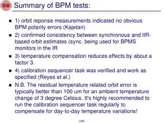
Pulse from the trigger suming analyzer board Thermometer
Analog vs Digital Signals from calibration board Pulse from the trigger summing analyzer board Data seen from the ROD using 1 calibration channel
Continuity • I have checked that the BCID’s (Bunch Crossing ID) from OC & PU agree with those of FEB ( except the consistent difference of “1” ) • The BCID would be reset at ~0xdef / 0xde7 and one has to take that into consideration when making comparison • All BCID’s originates from the same “BCRST” from the TTC • The trigger is synchronous with the 40 MHz clock (either from the PTG or a clock divider) • At trigger rate 100 kHz, we see regular intervals of BCID’s (such as 400 for ~100 kHz) between consecutive events, ie. • eg. BCID(i+1)– BCID(i) = 400 ( in this example and taking care of the 0xdef resetting etc.) No missing or skipped events • At trigger rate 100 kHz, we occassionally see irregular intervals of BCID’s There are events skipped by the FEB because FEB needs ~9.6 µs for digitization
Incidences of discontinuities vs trigger rate • At trigger rate 100 kHz, FEB is quite unstable but I have managed to measure at certain rates • Apparently, events are just skipped at higher rates but the data do not seem to be over-written
Noise RMS of the pedestals Comparion of noise measurements Not surprising probably because our events are separated by the same time interval and there is no overlap between events
Overnight long runs and “free service” • I have run the system (ROD-Glink-FEB) overnight • 4 bad events out of ~2108 events (as the data recovered in the next event) • ~10K of bad events of out of ~2108 events when the data don’t recover immediately after one bad event • We even sometimes provide free service for people outside BNL to use our entire system to make sophisticated measurements, though I personally prefer our service is not free but more profitable. • A few weeks ago, we have set up necessary software for E. Ladygin to make various measurements for his pre-shaper in HEC. We provide the script and he could just use it to run to take millions of events using our setup (ROD, FEB etc.) • It shows how robust and reliable our system is.
E. Ladygin’s noise measurement at BNL for his pre-shaper This includes measurements of the amplitudes of the pulses, averages and RMS’ of the pedestals for all 64 channels etc.
Summary • In the past ~year, we have set up, integrated and tested a system with the ROD at the end of the chain, that can be used to take serious calibration/physics measurements. • We have done a lot of debugging and got help from all the different board designers of the LArG/Atlas collaboration. • Now it has attained a state that is stable and robust enough to take sophisticated measurements, even by people outside.