Download
1 / 17
170 likes | 280 Vues
Project triggered by : K. Schindl and R. Cappi Hardware : J. Belleman ( PU amplifiers ) T. Bohl, W. Hofle, F. Pedersen, V. Rossi ( Signal processing ) F. Caspers, J.L. Gonzalez, J. M. Lacroix, J.M. Roux ( Kickers )

E N D
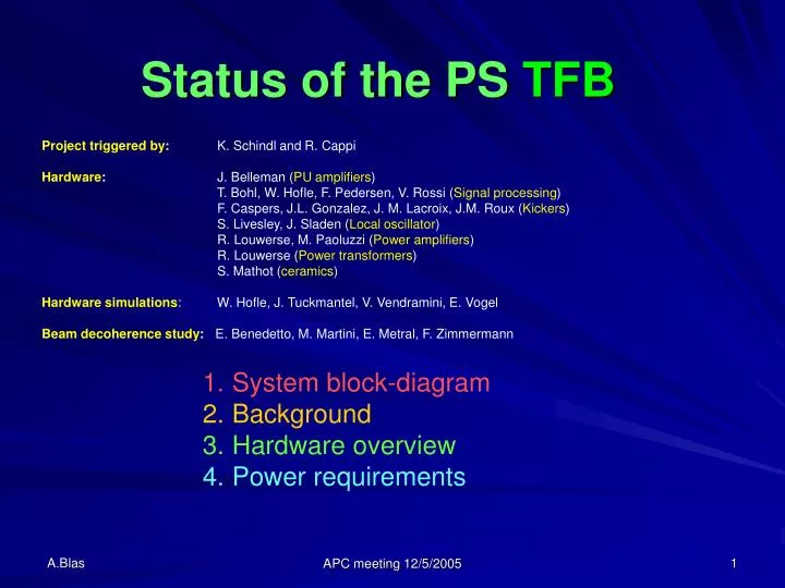
Project triggered by: K. Schindl and R. Cappi Hardware: J. Belleman (PU amplifiers) T. Bohl, W. Hofle, F. Pedersen, V. Rossi (Signal processing) F. Caspers, J.L. Gonzalez, J. M. Lacroix, J.M. Roux (Kickers) S. Livesley, J. Sladen (Local oscillator) R. Louwerse, M. Paoluzzi (Power amplifiers) R. Louwerse (Power transformers) S. Mathot (ceramics) Hardware simulations: W. Hofle, J. Tuckmantel, V. Vendramini, E. Vogel Beam decoherence study:E. Benedetto, M. Martini, E. Metral, F. Zimmermann Status of the PS TFB • System block-diagram • Background • Hardware overview • Power requirements APC meeting 12/5/2005
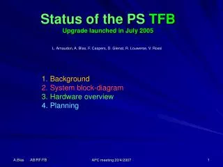
PS TFB Block diagram Blue boxes represent new hardware APC meeting 12/5/2005
PS TFB Background 05/98 First meeting, start of the PS TFB project 01/03 Project taken over by rf – kicker under BDI responsibility Status: 3kW Power amplifiers available (100 kHz HP cutoff !) Horizontal magnetic kicker ordered 10/03 Successful test of a new electronic prototype and Pick-up amplifiers with the old kicker/amplifier pair 01/04 H kicker Delivered, Ceramic pipe not vacuum tight after brazing (weak metallization) 10/04 Order placed for re-metallization (SCT) and new ceramic rings (Hiperceramics) Transition pieces redesigned 12/04 Kickers measured by rf team (F.C., T.K.) because of the absence of resource from BDI. Result: bandwidth below requirements – can not cope with kicker ripple. APC meeting 12/5/2005
PS TFB Pick-up amplifiers (J. Belleman) Were ready in October 2003 for the MD session. BW: 20 kHz – 40 MHz 80 dB dynamic range (compatible with ions). APC meeting 12/5/2005
PS TFB Electronic core (V. Rossi) Prototype has been tested in October 2003 for the MD session. Successful test although the automatic delay was not fast enough to cope with acceleration New design ongoing using the same hardware as for LHC (VME board with integrated control interface via the VME bus) Should be ready in spring 2006. APC meeting 12/5/2005
PS TFB Clock generation (J. Sladen) 1 GHz DDS Available since mid-2004 Will receive the frequency program from the PS central building and output the 160*Frev (< 80 MHz). This is well below its capabilities (400 MHz) APC meeting 12/5/2005
PS TFB Requirements • Initial requirements: R. Cappi 1999 • Damping of a +/-1.5 mm oscillation (H only, not V) within 100 turns (200 µs) • Bandwidth: [10kHz - 20 MHz] (q = 0.1 and 20 MHz kicker ripple) • Material ordered • 2 x 3 kW (2ms); 2 x 200 W (CW) amplifiers • BW [100 kHz - 20 MHz] • 12.5 Ωmagnetic kickers • Updated requirements: • Damping of a +/- 3 mm oscillation (H & V) with a time constant Td = 50 µs (cf. M. Martini) • Bandwidth: [10kHz - 30 MHz] (q = 0.1 and 30 MHz kicker ripple) APC meeting 12/5/2005
PS TFB Power Amplifier (M. Paoluzzi) 100 kHz – 35 MHz, 3kW – 2ms, 200W - CW Available since 2001 The bandwidth doesn’t allow handling the first Betatron line (40 kHz @ q = 0.1) The first Betatron line is intrinsically stable for q < 0.5, but the amplitude-phase response of the amplifier makes it unstable => compensation circuit to be developed. APC meeting 12/5/2005
Power amplifier frequency response APC meeting 12/5/2005
PS TFB Kickers (J.L. Gonzalez, F. Caspers) Strip-line Magnetic OR Cheap, Wide BW, both planes in one tank Lower kick (50 times less in H), need an impedance transformer with the available amplifiers Greater kick (50 times more for the same power in the horizontal plane) Expensive, limited bandwidth (not compatible with kicker ripple) APC meeting 12/5/2005
PS TFB Relation between fields and amplitude decay Assuming a linear decay in saturation mode = 1/e in Td (conservative approach) At PS injection: p =2.14 GeV/c TREV = 2.26 10-6 s β = 0.915 L = 0.9 m βH,V = 22 m E: [V/m] B: [V.s/m2] ⇔ ∆u : Steering error [m] Td : requested damping time (1/e) [s] APC meeting 12/5/2005
PS TFB Required power for the Strip-line kicker For the strip-line kicker where B = μ0E/377 η : kick efficiency (electrode shape + average Betatron phase) g : gap between electrodes = 14 cm (H) ; 6 cm (V) ZC : 112.5 or 50 Ω (practical values for transformers) ∆u : initial steering error Td : requested damping time (1/e) ⇒ P ≥ 2 x 1764 W for the most demanding beam pilot with 3 mm initial error => Td = 50 μs η=0.5 ZC=112.5 Ω – strip-line, β = 22 m APC meeting 12/5/2005
PS TFB Required power for the magnetic kicker For the 12.5 Ωmagnetic kicker with 0.13 Gauss/A (negligible electric effect) ∆u : initial steering error Td : requested damping time (1/e) η : kick efficiency (average Betatron phase) ⇒ P ≥ 2 x 36 W for the most demanding beams pilot with 3 mm initial error andTd = 50 μs η =0.5 APC meeting 12/5/2005
PS TFB Remarks concerning the kickers The 64 ns transit time measured on the magnetic kicker makes it incompatible with the request for 30 MHz BW (injection Kicker ripple) Dividing the magnetic kicker length by a factor 3 would be ok for the BW (9 times more power required = 330 W for the pilot beam) The strip-line kicker fulfills all LHC beams requirements with 1.8 kW if located at a favorable position: β = 22 m. Fitting both planes in one tank would required 3.5 kW per amplifier in the less favored plane: β = 11 m. This means that no more than 2.8 mm would be tolerated with 3 kW in this plane. APC meeting 12/5/2005
PS TFB Impedance matching transformers (R. Louwerse) Input impedance: 12.5 Ω Output impedance: 112.5 Ω (x9) Each coax: 37.5 Ω = two 75 Ω in // Voltage gain = 3 BW: 2kHz – 40 MHz up to 3 kW APC meeting 12/5/2005
PS TFB Choices to be made A strip-line H and V should be made available in 2006 We could then have a complete operational setup that could cope with all LHC beams in the horizontal plane (only 2.8 mm error – instead of 3mm - accepted in the vertical plane). This means resources (see next slide) Future possible upgrade Vertical kicker in a separate tank to provide some headroom (now limited to 2.8 mm). This also means resources (see next slide) APC meeting 12/5/2005
PS TFB Budget • No more money allocated to the project! • 260 kCHF need to be found to supply with an H/V strip-line damper in 2006. • 150 k: modification of 6 Power amplifiers • 15 k: redesign of the strip-line kicker (includes documentation) • - 8 k: impedance matching transformers (includes shielding boxes and mechanical setup) • - 10 k: 3kW power loads (includes mechanical setup) • 20 k: Power/interlock control system • 8 k: Water system (connections, detection) • 40 k: Electronic system (VME crate, circuits, spares) • 5 k: Cabling (within racks, in ring) • 6 k: Unexpected Total: 260 kCHF Future possible upgrade 60 k : Design and construction of a separate tank for the vertical plane APC meeting 12/5/2005