Download
1 / 31
330 likes | 637 Vues
THE FAILURE OF TETON DAM – A NEW THEORY BASED ON "STATE BASED SOIL MECHANICS". Paper: OSP-17. V.S. Pillai & B. Muhunthan. OUTLINE. Background Aspects Post failure investigations Focus of our investigations State dependent behavior of Teton core – Silt Analysis Conclusions.

E N D
THE FAILURE OF TETON DAM – A NEW THEORY BASED ON "STATE BASED SOIL MECHANICS" Paper: OSP-17 V.S. Pillai & B. Muhunthan
OUTLINE • Background Aspects • Post failure investigations • Focus of our investigations • State dependent behavior of Teton • core – Silt • Analysis • Conclusions
Location of Teton Dam • 64 km Northeast of Idaho falls • Across Teton river • Near Wyoming-Idaho border in the Teton mountain range
Design cross section of the dam at river valley section ( after IP, 1976)
El.5300 El.5200 A typical cross section of the dam at the right abutment (after IP, 1976)
Teton Dam-Zoned earth fill dam-405 ft. high • Part of a multi-purpose Irrigation and Power project (1972-75, USBR) • Construction of the dam completed and first filling started in November 1975 • Dam failed suddenly on June 5, 1976 when the reservoir level rose to El.5301.7 ft.
Leak Dam Failure – First Leakage • Around 7:00 am on June 5, 1976 dam personnel discovered a leak about 30 m from the top of the dam
Senator Frank Church (Idaho) • The anguished Senator Frank Church, flying over the disaster area, stated that: “This dam was built according to the latest state-of-the-art” “Nothing like this should have happened....Nothing like this could have happened, except for a fatal flaw either in the siting of the dam or in the design”
Post Failure Investigations • Independent Panel (IP) • Interior Review Group (IRG) • Documented well in literature • General conclusions: • Seepage piping and internal erosion • Hydraulic fracture • Wet seams • Differential settlement and cracking • Settlement in bedrock • Seepage through rock openings
Focus of Our Investigations • Low plasticity of the impervious core • Low placement liquidity index (LI) of the core • High compaction/Constrained modulus of the core • Crack potential of the core under low confining stresses/upper portion of the dam
Design compaction curve 1.70 1.65 1.60 Dry density (g/cc) 1.55 1.50 1.45 10 15 20 Water content (%) Teton core 25 Some properties of the impervious core – ZoneI
STATE BASED SOIL MECHANICS • State of soil is defined in a 3-D space (p, q, e or v) p‘-mean effective stress - (s’1+2s’3)/3 q - shear stress - (s1-s3) e - void ratio or v=(1+e) - specific volume • Limits to stable states of soil behavior – • SBS (p,q,e) • 2-D representation of the normalized state • boundary surface • Soils state in liquidity index-confining • stress space
FL CSL Soil states in normalized stress-space
Cam-clay regime X1 Soft X2 Dense (Hvorslev regime) X3 Possible soil states in v-lnp’ space
B A LI5=LI+0.5log(p‘/5) LI-lnp' diagram & q/p'-Equivalent liquidity diagram (after Schofield, 1980)
Family of critical state lines (Modified after Schofield and Wroth, 1968)
A1 A4 Typical element An Longitudinal section of the dam –(Schematic) (Modified after IP, 1976)
q q/p' = 3 q/p'~2 CSL q/p'~0.7 Crack Surface A2 A4 Cam-clay yield surface A3 A1 p' Unstable A1 Stable soft (Yield) A2 A4 – A3 NCL Stable dense CSL - Unstable Crack line (Fracture) p' q/p' = 0 q/p' = M q/p'= 2 q/p' = 3 v Stress path during construction - Conceptual
Soil elements at different depths El. 5300 El. 5200 Cross section of dam near right abutment
q q/p' = 3 q/p'~2 CSL q/p'~0.7 Crack Surface A2 A4 Cam-clay yield surface A3 A1 p' v Unstable A1 Stable soft (Yield) A2 A4 – A3 NCL Stable dense CSL - Unstable Crack line (Fracture) lnp' Stress path of a soil element during construction
Material parameters Critical State Parameter Value k 0.005 l 0.07 G 1.95 M 1.1 n 0.3 G (psf) 300000 p'c (psf) 12000
FINITE ELEMENT ANALYSIS • ABAQUS – FE software developed by Hibbitt, Karlsson and Sorenson Inc. • Critical state plastic material model and Porous elastic material model • *MODEL CHANGE option was used to simulate the construction of dam • SURFACE was used to draw the contours of q/p‘ ratio as well as LI5 variation
El.5301 Reservoir level Contours of q/p‘ ratio
CRACKED 3 Details of q/p ratio at the right abutment ( for q/p>3, Zone 1 cracked)
Prone for cracking Contours of equivalent liquidity LI5
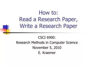
Conclusions • A transverse crack(s) or large opening(s) had developed in the core (Zone-1) to a maximum depth of 32 feet below the crest at the right abutment near Sta. 14+00 • When the reservoir level rose to the level of the deepest crack, water flowed freely barreling downstream into the chimney drain (Zone- 2) • A combination of low plasticity, low LI, its variation under the subsequent confining stress condition, played a key role in the cracking of the core • State based soil mechanics also explains the flaws of the findings by others and are provided in the Paper
Flooded City of Rexburg Thank you for your patience !