Download
1 / 44
450 likes | 1.82k Vues
Parallax BASIC Stamp ® Tutorial. Developed by: Electronic Systems Technologies College of Applied Sciences and Arts Southern Illinois University Carbondale http://www.siu.edu/~imsasa/est Martin Hebel mhebel@siu.edu With support from: Will Devenport, Mike Palic and Mike Sinno

E N D
Parallax BASIC Stamp® Tutorial Developed by: Electronic Systems Technologies College of Applied Sciences and Arts Southern Illinois University Carbondale http://www.siu.edu/~imsasa/est Martin Hebelmhebel@siu.edu With support from: Will Devenport, Mike Palic and Mike Sinno Sponsored by: Parallax, Inc. http://www.parallax.com/ Updated: 1/6/03 Version 0.96
Copyright Notice • Copyright 2002, Parallax, Inc. BASIC Stamp is a registered trademark of Parallax, Inc. • Parallax, Inc. and participating companies are not responsible for special, incidental, or consequential damages resulting from any breach of warranty, or under any legal theory, including lost profits, downtime, goodwill, damage to or replacement of equipment or property, nor any costs of recovering, reprogramming, or reproducing any data stored in or used with Parallax products. • Unmodified distribution of this tutorial is allowed. • Modifications to this tutorial are authorized for educational use internal to the school’s program of study. This copyright notice and development credits must remain.
Use of the Tutorial • This tutorial is for novices in programming the BS2 from Parallax, Inc. For advanced use please refer to your BASIC Stamp Manual, help files and other sources. • The tutorial uses the Board of Education (BOE) as the primary carrier board for the BS2, though other boards and configurations may also be used. • The majority of the tutorial is compatible with the HomeWork board and the BASIC Stamp Activity Board except where noted. • We welcome any constructive feedback you wish to provide. A feedback page and survey are located at: http://imsinet.casa.siu.edu/bs2_tutorial/feedback.htmIf this link is no longer active, please contact Parallax at stampsinclass@parallax.com.
Section 1: BASIC Stamp 2 Anatomy • Microcontrollers • BASIC Stamp Components • BASIC Stamp 2 Pins • BASIC Stamp 2 Versions • Running a Program • Carrier and Experiment Boards • Power Connections • Data Connections • Serial Data Connectors • I/O Connections • Component Power Connections • Connecting Components • Breadboard Connections • Other Features
Microcontrollers • Microcontrollers can be thought of as very small computers which may be programmed to control systems such as cell phones, microwave ovens, toys, automotive systems, etc. • A typical household has upwards of 25 to 50 microcontrollers performing embedded control in numerous appliances and devices. • The BASIC Stamps are hybrid microcontrollers which are designed to be programmed in a version of the BASIC programming language called PBASIC. • Hardware support on the module allows fast, easy programming and use.
BASIC Stamp Module Components Serial SignalConditioningConditions voltagesignals between PC serialconnection (+/- 12V) and BASIC Stamp (5V) 5V RegulatorRegulates voltageto 5V with a supply of 5.5VDC to 15VDC EEPROMStores the tokenized PBASIC program. ResonatorSets the speed at whichinstructions are processed. Interpreter ChipReads the BASIC program from the EEPROM and executes the instructions.
BASIC Stamp 2 Pins Pin 1: SOUT Transmits serial data during programming and using theDEBUG instruction Pin 2: SIN Receives serial data during programming Pin 22. RES Reset- LOW to reset Pin 3: ATN Uses the serial DTR line togain the Stamps attention for programming. Pin 21. VDD Regulated 5V. Pin 4. VSS CommunicationsGround (0V). P0 P15 P1 P14 P2 P13 P3 P12 Pins 5-20:Input/Output (I/O)pins P0 through P15 P4 P11 P5 P10 P6 P9 P7 P8 Pin 24. VIN Un-regulated input voltage (5.5-15V) Pin 23. VSS Ground (0V)
Running a Program • The program is tokenized,or converted into symbolic format. • The tokenized program is transmitter through the serial cable and stored in EEPROM memory. Tokenizer • The Interpreter Chip reads the program from EEPROM and executes the instructions reading and controlling I/O pins. The program will remain in EEPROM indefinitely with or without power applied. • A program is writtenin the BASIC Stamp Editor
Power Connections Many carrier boards, such as the BOE, have an additional 5V regulator to supplement the on-module regulator. • The Board of Education may be powered from either: 6-15VDC Wall Transformer,center positive. 9V Battery
Data Connections • A serial cable (modem cable) is connected between BASIC Stamp and the computer’s serial communication port (COM port). • Serial means that data is sent or received one bit at a time. • The serial cable is used to download the stamp with the program written in the text editor and is sometimes used to display information from the BASIC Stamp using the DEBUG instruction. • Ensure that you use are using aStraight-Through cable (pins 2and 3 do not cross from end-to-end) as opposed to a Null-Modem cable (pins 2 and 3 cross). • There are different connectors fordifferent computer hardware.
Serial Data Connectors The cable is typically connectedto an available DB 9 COM port. Newer systems mayonly have USB portsand require a USB-to- Serial Adapter. A DB 25 to DB 9 adapter may be needed on older systems
I/O Connections A connection to the I/O pins is also available on the ‘App-Mod’ header. The P8 connection isavailable on the headernext to the breadboard area. • Code, such as HIGH 8 will be written for the BASIC Stamp. This instruction will control a device connected to P8 of the controller.
Component Power Connections +5V (Vdd) 0V or ground (Vss) Supply Voltage (Vin) • Power for the components are available on headers also. NOTE: Use of Vinmay cause damagingvoltages to be applied to the BASIC Stamp.Use only under directeduse!
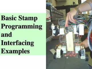
Connecting Components • Of course, an important aspect to any BASIC Stamp project are the components that will be connected to the I/O pins of the Stamp. • The carrier boards allow quick connections for the components.
Breadboard Connections Each row in each half of the breadboard are electrically the same point. There exist no connections between the headers and the breadboards or in columns on the breadboard. Components are connected between rows and to the headers to make electrical connections. Components should NOT be connected on a single row or they will be shorted out of the circuit. • Breadboard are rows of connectors used to electrically connect components and wiring.
Vdd (5V) I/OPin • This image is the Board of Education with several components connected. • The connectionson the breadboardcreate a completepath for currentto flow.
Other Features Servo Header Connectors ProgrammingPort Power-On LED Reset Button to restart theprogram on the BASIC Stamp
Section 3: BASIC Stamp Editor • BASIC Stamp Editor • Identifying the BASIC Stamp • Writing the Program • Downloading or Running Code • Tokenizing and Errors • Commenting Code • DEBUG Window • Memory Map • Preferences • Help Files • Instruction Syntax Convention
BASIC Stamp Editor • The BASIC Stamp Editor is the application that is used to write, edit, and download the PBASIC programs for the BASIC Stamp. • The software may be downloaded for free from Parallax. Some installations of Windows 95 and 98 may require an additional file to be installed. Please see the information on the download page for more information. • Once installed, the Stamp Editor will be available on your desktop, and as a menu option underStart Program Files Parallax Inc
Identifying the BASIC Stamp • Connect the BASIC Stamp carrier board to your computer with a serial cable. • Power-up your BASIC Stamp carrier board. • Use the Identify button to verify communications to your BASIC Stamp.
Identification Errors • If the ID shows: • No Device Type • No Loopback • No EchoIt usually means the BASIC Stamp is not connected properly to the computer with a serial cable. • Verify the carrier board is connected to the computer with a serial cable, full-modem variety (not null-modem). • If your computer has multiple COM ports, try another. • If the COM port you are using is not listed, try adding it to the Stamp Editor using EditPreferences.
If the ID shows: • No Device Type • Loopback - Yes • Echo – YesIt usually means the BASIC Stamp is connected, but it has no power. • Verify the carrier board has power supplied and the power light is on (if available).
If the COM port cannotbe opened, it usually meansanother program has controlof the port. • Close any applicationswhich may be using the port, including terminal programs,dial-up programs, Palm Pilot programs, PC Anywhere, StampPlot and other communication programs. • If you cannot resolve the problem, if possible: • Test another person’s operational board on your computer using their cable and yours. • Test your board on another computer, preferably one that had a working BASIC Stamp. • Contact Parallax support: support@parallax.com
Writing the Program • BASIC Stamp programs are written in a version of BASIC called PBASIC entered into the BASIC Stamp Editor. • A program typically reads inputs, processing data, and controls outputs. • Programs must conform to the rules of syntax so that the BASIC Stamp can understand what you are telling it. DEBUG “Hello World”
Downloading or Running Code ‘{$STAMP BS2} DEBUG “Hello World” • Once a program is entered, the Run button (or Ctrl-R) is used to tokenize and download the program to the BASIC Stamp. • The Editor will request you indicate the style of BASIC Stamp you are using. DEBUG “Hello World” • The style may be selected from the menu, or by selecting your ‘color’ of your BASIC Stamp on the button bar. • A directive will be added to the top of your code.
Tokenizing and Errors • When a program is ‘Run’ the PBASIC code is converted to symbolic format called tokens. These are stored in ROM memory on your BASIC Stamp. • In order to tokenize your program, the code must to conform to the rules of syntax for the language. • If there are errors: • An error message will appear indicating a problem, the status turns red and code is highlighted. • Generally, the error can be found by looking before the highlighted area. • Read your code carefully looking for the syntax error or bug. In this example DEBUG is incorrectly spelled. • Code may be syntax checked without downloading by using the Syntax Check button.
Commenting Code • Comments, or remarks, are descriptions or explanations the programmer puts in the code to clarify what it is doing. • Comments are signified by leading with an apostrophe. • Comments are NOTsyntax checked, nordo they increase thesize of your program.So comment oftenand at length!
DEBUG Window • Programs may contain a DEBUG instruction. This instruction sends serial data back to the computer on the serial cable. • When DEBUG is present in a program, a DEBUG window will open in the Editor to view the returning data. • The DEBUG button may be used to manually open a DEBUG window.
Memory Map • The Memory Map button will open the BASIC Stamp window. • This window shows how program (EEPROM) and variable memory (RAM) is being utilized. • Note that the program is stored in memory from bottom-up. RAM Memory: I/O Control RAM Memory: Variables EEPROM Memory:Program space of tokenized program
Preferences • Under the Preferences button you may: • Change color, font, and tab spacing for the text editor and debug screen. • Set the COM port on which the stamp is connected to, or be in automatic detection mode. • Modify the DEBUGsettings. • You are encouraged tolook through the availablesettings to become familiarwith them.
Help Files • There exists a help file that is very thorough at assisting you with any problems or questions you might have about instruction syntax or use while programming. • By highlighting an instruction and pressing F1, the help files will open to display information on that instruction. • Help provides a description, syntax (format) and example for each instruction.
Instruction Syntax Convention • BASIC Stamp instructions follow a common code convention for parameters (parts) of instructions. • Take for example the FREQOUT instructions, which may be used to generate tones from a speaker:FREQOUTPin, Period, Freq1 {, Freq2} • The instruction requires that the Pin, Period, and Freq1 is supplied and that each are separated by commas. • Optionally, the user MAY provide Freq2 indicated by braces { }. • While PBASIC is NOT case-sensitive, the common convention is to capitalize instructions, and use 1st letter upper-case for all other code.
Section 4: Input, Output, and Processing • Inputs, Processing, and Outputs • Stamp I/O • Debugging • DEBUG Instruction • DEBUG for Program Flow Information • Using DEBUG ? to Display Status
Inputs, Processing, and Outputs • Any system or program accepts input, process information, and controls outputs. • The BASIC Stamp, and other microcontrollers, specialize in using input devices such as switches, and controlling output devices such as LEDs (Light Emitting Diodes). • A program, written in a form of the BASIC language called PBASIC, is used for processing by writing code that instructs the BS2 what actions to take. Input Processing Output
Stamp I/O • There are 16 I/O (Input/Output) pins on the BS2 labeled P0 to P15. These are the pins through which input and output devices may be connected. • Depending on the code that is written, each pin may act as an input to read a device, or as an output to control a device.
Debugging • Debugging refers to the act of finding errors in code and correcting them. There are 2 types of errors which can be made when coding: Syntax errors and Logical errors. • Syntax errors are those that occur when the editor/compiler does not understand the code written.An example would be: GO TO MainThe PBASIC tokenizer, which takes our code and puts it in a form the BS2 understands, does not have an instruction called GO TO (it has one called GOTO). This section of code would be flagged as having a syntax problem, which we identify and correct.
Logical errors are those which have a valid syntax, but fail to perform the action we desire.For example, our program runs, but it seems the LED is off an abnormally long time. Looking at the code we find the bug: PAUSE 50000 instead of PAUSE 5000.The PBASIC compiler was perfectly happy with a 50 second pause, but logically it was not what we wanted to happen. • Syntax errors are easily flagged when we try to run the program. Logical errors are more difficult because they require the programmer to analyze the code and what is occurring to determine the ‘bug’.
DEBUG Instruction • The DEBUG instruction provides a valuable tool for the programmer. • It provides a means of real-time feedback in debugging to: • Observe program execution. • Observe program values. • It also allows the programmer to use a very sophisticated output device – A computer monitor. • When a DEBUG instruction used, the Stamp Editor’s DEBUG window will open and display the data.
When we run, or download, a program to the BS2, the program is transferred serially from Stamp Editor though a serial COM port to the BASIC Stamp. • Using the same serial connection, the BS2 can transfer data back to the Stamp Editor to be displayed. • Throughout this tutorial we will use DEBUG for various indications and describe the syntax used.
DEBUG for Program Flow Information • Sometimes it is difficult to analyze a problem in the code because we have no indication where in the program the BS2 is currently at. A simple DEBUG in the code can provide feedback as to flow. • DEBUG “A description of code to be performed”,CRCR is short for carriage return to move the cursor to the next line. • DEBUG could be used to help identify the ‘bug’ where 50000 was typed instead of 5000.
Using DEBUG ? to Display Status • Another simple use of DEBUG is to indicate the status of an output or input. • DEBUG ? OUTpin • Say for example the P8 LED was not lighting. Is it a code problem (OUT8 not going low?) or an electronics problem (LED in backwards?). • Using DEBUG inkey spots, the status of P8 can be verified.
Digital Inputs • Just as P0 – P15 on the BASIC Stamp can act as outputs to control devices, they can act as inputs to read devices, such as switches. • By default, the BASIC Stamp I/O pins will act as inputs unless specifically set to be an output. In our code we specify the I/O as inputs out of good programming habits. • INPUT pin • INPUT 10
Classwork and Homework • During class, work on your check-off sheet. • For our next class, write a one page essay describing how the boe-bot works. • Remember to follow the formatting guidelines for our class on the Resources page. • Your essay should be organized with an introductory paragraph and a concluding paragraph. • You are free to use any of the reference materials found online, but cite your sources.