Download
1 / 30
300 likes | 500 Vues
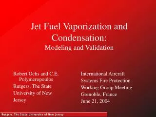
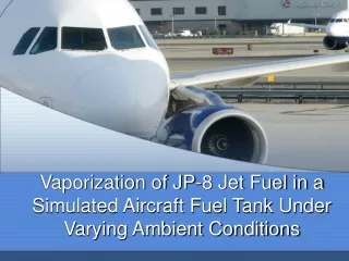
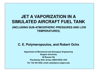
JET A VAPORIZATION IN A SIMULATED AIRCRAFT FUEL TANK (INCLUDING SUB-ATMOSPHERIC PRESSURES AND LOW TEMPERATURES) . C. E. Polymeropoulos, and Robert Ochs Department of Mechanical and Aerospace Engineering Rutgers University 98 Bowser Rd Piscataway, New Jersey, 08854-8058, USA

E N D
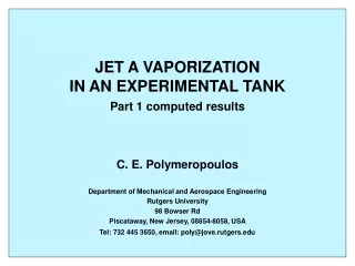
JET A VAPORIZATION IN A SIMULATED AIRCRAFT FUEL TANK(INCLUDING SUB-ATMOSPHERIC PRESSURES AND LOW TEMPERATURES) C. E. Polymeropoulos, and Robert Ochs Department of Mechanical and Aerospace Engineering Rutgers University 98 Bowser Rd Piscataway, New Jersey, 08854-8058, USA Tel: 732 445 3650, email: poly@jove.rutgers.edu
Motivation • Combustible mixtures can be generated in the ullage of aircraft fuel tanks • Current effort in minimizing explosion hazard • Present objective of the present work is: • prediction of the influence of different parameters involved in the evolution and composition of combustible vapors • The tank ambient pressure and temperature • The fuel and tank wall temperatures • The composition and the amount of fuel in the tank • assessing the flammability of the resulting air-fuel mixtures
Outline • Brief background discussion • Description of the model • Comparisons with experimental data • Discussion of model results • Conclusions
Mass Transfer Considerations • Natural convection heat and mass transfer • Liquid vaporization • Vapor condensation • Variable Pa and Ta • Vented tank • Multicomponent fuel
Assumptions used for Estimating Ullage Vapor composition • Well mixed gas and liquid phases • Spatially uniform and time varying temperature and species concentrations in the ullage and in the evaporating liquid fuel pool • Quasi-steady transport using heat transfer correlations, and the analogy between heat and mass transfer for estimating film coefficients for heat and mass transfer • Low evaporating species concentrations • The time dependent liquid fuel, and tank wall temperatures, and the tank pressure are assumed known
Additional Assumptions • Gases/vapors follow ideal gas behavior • Tank pressure is equal to the ambient pressure • Condensate layer forms on the tank walls • Condensate at the tank wall temperature • No out-gassing from the liquid fuel, no liquid droplets in the ullage, no liquid pool sloshing • Fuel consumption neglected
Computational Method • Given: • The tank geometry • The fuel loading • A liquid fuel composition • The tank pressure, and the liquid fuel and the tank wall temperatures as functions of time (experimental data) • The previous relations allow computation of the temporal variation of ullage gas composition and temperature
Jet A Characterization • Jet A is a complex multi-component fuel • Components are mostly paraffin, and to a lesser extend cycloparaffin, aromatic, olefin, and other hydrocarbons • Jet A specifications are expressed in terms of allowable ranges of properties reflecting the physical, chemical and combustion behavior of the fuel • The composition of a Jet A sample therefore depends on its source, on weathering, etc
Data for Jet A Characterizationwas based on Woodrow’s (2002) data • Jet A samples with flash points between 37.5 °C and 59 °C were characterized using chromatographic analysis • The characterization was in terms of equivalent C5 to C20 normal alcanes • Equilibrium vapor pressures computed with the resulting compositions were in good agreement with measured data • For comparisons with test tank results the model used fuel compositions from Woodrow’s data having flash points similar to the fuel samples used with the experimentation
Jet A Compositions used for Comparisons with Experimental Data
Comparisons with Experimental Data • Data on ullage temperature, and total hydrocarbon concentration with test tank at ambient pressure (Summer, 1997) • Samples with: 322.3 K < F.P.< 325.2 K • Data on ullage temperature, and total hydrocarbon concentration with test tank in altitude chamber (Ochs, 2004) • Samples with: 322.3 K < F.P. < 319.5 K • Data data from aircraft fuel tank (Summer, 2004) • Samples with various F.P.
Ullage Vapor Lower Flammability Limit • The lower flammability limit (LFL) of ullage vapor is not well defined. • Empirical definitions (used by Shepherd 2000) • For most saturated hydrocarbons the 0°C F/A mass ratio at the LFL is 0.035±0.05 (Kuchta,1985) • Le Chatelier’s rule: at the LFL LR =1 where, Note: Use of Le Chateliers’s rule with the present equivalent n alcane species Jet A characterization needs further examination
Conclusions • The temporal evolution of Jet A fuel vapor in experimental tanks was estimated using perfectly mixed fluids due to natural convection, and correlations based on the analogy between heat and mass transfer • Principal required inputs to the model were the tank geometry, the fuel loading, a component characterization of the liquid fuel, the tank pressure, and the temperature history of the liquid fuel and the tank walls. • Liquid Jet A was characterized using mixtures of C5-C20 n-alcanes with flash points equivalent to those of the samples used with the experimental test tanks • There was good agreement between measured and computed total Jet A vapor concentrations within a constant pressure test tank, and also within one undergoing pressure and temperature variations similar to those encountered with aircraft flight
Conclusions (continued) • The model was used for detailed examination of evaporation, condensation and venting in the test tanks, and of the observed variations in total hydrocarbon concentration • The model was also used for estimating the effect of different parameters on the ullage F/A mass ratio • The temperature of the liquid fuel had a strong influence on the F/A • The effect of fuel loading was of minor significance, except for small fuel loadings. Of importance, however, is the potential of increased liquid fuel temperatures at low fuel loading • Of major significance was the choice of liquid fuel composition, which was based on previous experimental data with samples differentiated by their flash point
Conclusions (continued) • The flammability of the ullage vapor was assessed • Using as criterion a previously proposed limit range of F/A mass ratios • Le Chatelier’s ratio with ullage species mole fractions computed with C5-C20 liquid fuel compositions • For the cases considered the two approaches yielded comparable LFLs. However, prediction of the LFL of Jet A requires additional consideration, especially with the use of an equivalent fuel composition • The model needs to be applied to different flight conditions using data from aircraft fuel tanks
Acknowledgment Support for this work was under the the FAA/Rutgers Fellows Program, provided by the the Fire Safety Division of the FAA William J. Hughes Technical Center, Atlantic City, New Jersey, USA