Download
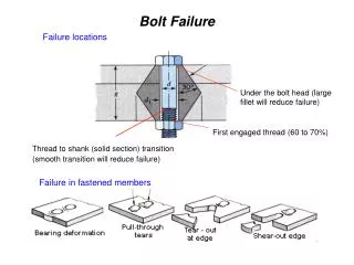
1 / 34
370 likes | 578 Vues
Bolt Modeling workbench. Application | Special | Bolt Modeling. T o p R B E. T o p R B E. T o p R B E. B a r. Mid RBE. B a r. B a r. B a r. B a r. B o t t o m R B E. B o t t o m R B E. B o t t o m R B E. Bolt-Head. Bolt Modeling | Bolt-Head

E N D
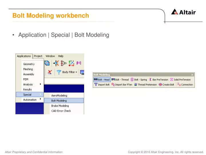
Bolt Modeling workbench • Application | Special | Bolt Modeling
T o p R B E T o p R B E T o p R B E B a r Mid RBE B a r B a r B a r B a r B o t t o m R B E B o t t o m R B E B o t t o m R B E Bolt-Head • Bolt Modeling | Bolt-Head • A bolt is modeled as 2 parts, the head and the tail. The head portion can be modeled in one of several ways. Most common type is top and bottom RBE connected by a bar element
Edge Based Bolt-Head (Ex:Cover.gda) • To create the head part of the bolt hole, the bolt holes are identified by manually by selecting the single edge on top and bottom of the holes. Multiple bolts can also be created by selecting top and bottom edges for each bolt hole
Face Based Bolt-Head (Ex:Cover.gda) • It is possible that a model can have a lot of bolts and it makes it difficult to manually pick all the edges. So the another option is provided to model bolt heads on all the hoes on a face. User need to select the face(s) where bolt head sits and specify the bolt hole diameter range.
T o p R B E T o p R B E B a r B a r B o t t o m R B E B o t t o m R B E B o t t o m R B E Bolt-Thread • Bolt Modeling | Bolt-Thread • The thread portion of the bolt can be modeled in one of several ways
D o w n S e c t I o n s Configuration of bottom RBE • Down • Up • Both • Sections
Edge Based Bolt-Thread (Ex:Carrier.gda) • To create the thread part of the bolt hole, the bolt holes are identified by manually selecting the single edge on top of the holes. Multiple bolts can also be created by selecting top edges for each bolt hole
Face Based Bolt-Thread (Ex:Carrier.gda) • User need to select the face(s) and specify the bolt hole diameter range.
File based bolt modeling (Ex: Diff_Case.gda) • Bolt Modeling | Import Bolt • Bolts can also be modeled by directly importing the bolt definition file. Importing bolt will create both head and thread portion of bolts. There are three different blocks in the file called BOLT, HEAD_DEF and THREAD_DEF define bolt, head and thread respectively. The complete definition for each key work of the bolt definition file is available in F1 help. • Sample bolt definition file (BoltDefinition.dat).
Bar Pretension • Bolt Modeling | Bar Pretension • User can model the pre tension in the tightened bolt in several ways. The tension in the tightened bolt is modeled by creating RBEs, Bars and force by selecting the edges on bolt hole. This option is refered as “Edge Based”. • Different types of Bar Pretension are • Through • Threaded
T o p R B E B a r F o r c e B o t t o m R B E T o p R B E T o p R B E T o p R B E T o p R B E B a r B a r B a r B a r F o r c e F o r c e F o r c e F o r c e B o t t o m R B E B o t t o m R B E B o t t o m R B E B o t t o m R B E Through / Threaded (Edge Based)
Through (Ex: BarPretension.gda) • This type can be modeled by selecting the top edge of bolt shank hole and bottom edge of threaded hole
RBE Based (Ex:RBEBased_BarPretension.gda) • Bar pretension can also be modeled by directly selecting the RBEs/Nodes referred as “RBE Based” and “Node Based” respectively.
Solid Pretension • Bolt Modeling | Solid Pretension • User can model the pre tension in the tightened bolt by applying solid pretension for the following solver • Abaqus • Ansys • Nastran • Permas • There are two ways of creating Abaqus bolt • Creating pretension face • Using existing pretension face
Abaqus – Creating pretension cut • Ex: Bolt.gda • Define the plane where to create the pretension cut.
Abaqus – Using existing pretension cut • Ex: Bolt_With_Cut.gda • Select the pretension cut face in the bolt
Ansys, Nastran, Permas solid pretension • There are three ways of creating Ansys, Nastran and Permas bolt • Creating pretension cut • Using existing pretension cut • Using the faces apart in the bolt • Creating pretension cut (Ex: Bolt.gda) • User need to define the plane to create pretension cut and solid pretension based on solver • Using existing pretension cut (Ex: Bolt_With_Cut.gda) • User need to select the existing pretension cut to create solid pretension based on solver • Using the faces apart in the bolt (Ex: Bolt_With_Face_Apart.gda) • User need to select the two face apart in the bolt to create solid pretension based on solver
Solid Bolt • Bolt Modeling | Create Bolt • User need to define the axis and pivot point followed by the parameters • Templates can be exported/imported
Connection • Bolt Modeling | Connection • Creates connection between bodies automatically • Rigid Bar • Equivalence • RBE
Rigid Bar (Ex: Connection.gda) • Bolt Modeling | Connection | RBAR • User can select either the option between two bodies two bodies (Rigid body/Bar body) or all bodies to connect the free nodes by RBAR by identifying the matching nodes based on the tolerance value specified.
RBAR Rigid Bar (Contd.)
Equivalence (Ex: Connection.gda) • Bolt Modeling | Connection | Equivalence • RBE center nodes and bar body free nodes, which lie within the given tolerance will get equivalence.
Node equivalence Equivalence (Contd.)
RBE (Ex: Connection.gda) • Bolt Modeling | Connection | RBE • User need to select dependent and independent body, based on the tolerance specified the matching nodes will be connected by a RBE
Dependent body Independent body Connecting RBE RBE (Contd.)