Download
1 / 41
510 likes | 1.17k Vues
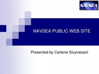
“SYSTEMS ENGINEERING APPLICATIONS IN NAVSEA-CARDEROCK’S INNOVATION CENTER”. Presentation to Naval Postgraduate School Systems Engineering & Analysis Program 16 Oct 2003 David W. Byers Director, I nnovation Center (Code 011). Outline . I nnovation Center Overview

E N D
“SYSTEMS ENGINEERING APPLICATIONS IN NAVSEA-CARDEROCK’S INNOVATION CENTER” Presentation to Naval Postgraduate School Systems Engineering & Analysis Program 16 Oct 2003 David W. Byers Director, Innovation Center (Code 011)
Outline • Innovation Center Overview • Systems Engineering Application Philosophy • Example of Application in “Surface Combatant Optimized for Unmanned Vehicle Operations (SCOUVO)” • Summary • Discussion D. W. Byers/NAVSEA-Carderock 011
The Innovation Center Defined • “Innovation” = Creativity + Implementation • NAVSEA-Carderock Innovation Center Charter: “Provide a mechanism to have 3-to-6-member, full-time, multi-disciplined, dedicated teams investigate high risk/high payoff solutions to Navy engineering and R&D challenges or problems and perform accelerated exploration of new ideas” D. W. Byers/NAVSEA-Carderock 011
Unmanned Underwater Vehicle (UUV) [‘89] Semi-Submerged Surface Ship [’89] “Tipjet” Vertical Launch & Recovery (VLAR) Sensor Platform [‘89] Quiet Surface Ship Propulsor/Hull Concepts [’90] Automated Ship Hull Husbandry Vehicle [‘91] Advanced Submarine Stern Cluster [’92] Advanced Submarine Sail Cluster [’92] 21st Century Destroyer Technology Drivers [‘92] System Technology Assessment Resource (“STAR”) [’93] “Autonomic” Ship [‘93] Maritime Pre-positioning & Sustainment Ship System [’94] Dual Use and Commercialization of Technologies(“DUCT”) [’94] Small Combatant [’95] Littoral Warfare Fire Support Ship & Reduced Manning [’95] Concurrent Engineering of Layered Systems (“CELS”) [’96] Leading Edge Advanced Prototyping for Ships (“LEAPS”) [’96] Integrated Hull & Deck Topside Design (“DeckOps 2020”) [’97] Low Signature Options for Future Submarines (CLASSIFIED) [’98] Low Maintenance Surface Ships [’98] “Carrier Islands” [’99] Project “Blackjack” (Mobile Forward Expeditionary Operating Base/Craft) [’00] Unmanned Surface Vehicle [’01] Advanced Logistics Delivery System (ALDS) [’02] Surface Combatant Optimized for Unmanned Vehicle Operations (SCOUVO) [’03] Innovation Center Project Record (24) D. W. Byers/NAVSEA-Carderock 011
AUTOMATED UNDERWATER HULL MAINTENANCE AND MONITORING SYSTEM AHMV Field Test on USS CAPE ST GEORGE 5 3/12/2014 D. W. Byers/NAVSEA-Carderock 011
Systems Engineering Application Philosophy • “Defining the Problem” = Team Restatement of Initial Charter absolutely vital first step (“Requirements Definition”) • Must establish valid & measurable (within project time & resource constraints) metrics • “Divergence/Convergence” fundamental to IC Process • “Brainstorming” key tool in Divergence Phase • After convergence to most promising alternatives, standard systems engineering process applied D. W. Byers/NAVSEA-Carderock 011
“CV Islands” Project -Finalized Charter and Evolution Final: Develop and Assess Integrated Aircraft Carrier Island Concepts and Corresponding Implementation Plans Capable of Significantly Advancing Naval Warfare at Reduced Total Ownership Cost Original: Develop integrated aircraft carrier island & topside design system concepts capable of meeting future aircraft carrier requirements envisioned for the CVNX which can be progressively incorporated in hulls beginning with CVN 77 and corresponding technology development plans High Risk/High Pay-Off
“CV Islands” Metrics (“Success Criteria”) • Reduced Total Ownership Cost (TOC) • Positive Impact on Sortie Rate • Enhanced Survivability (Susceptibility, etc.) • Minimize Flight Deck Impact • Reduced Accident Rate • Increased Flexibility of Aircraft Operations • Minimize Weight • Upgradeability
Systems Engineering Process Systems Balance Requirements Analysis Process Input Process Output Functional Analysis Design Loop Req’ts Loop Design Synthesis Validation/Evaluation Loop D. W. Byers/NAVSEA-Carderock 011
Surface Combatant Optimized for Unmanned Vehicle Operations (SCOUVO) - Team Charter “ Develop alternative design concepts for a near term1, relatively small2, high speed3, littoral warfare surface combatant that optimally integrates the operations of unmanned vehicles4 with the ship platform and the network-centric operational environment “ • 2015 • Less than 5000 tons • Greater than 45 knots • UAVs, USVs, UUVs, and UGVs
Mission Scenario • Four primary missions for SCOUVO • Intelligence, Surveillance and Reconnaissance (ISR) • Shallow Water Anti-Submarine Warfare (ASW) • Mine Warfare (MIW) • Small Boat Defense (SBD) • MIW chosen as reference mission • High degree of interaction between ship and UVs • Most taxing on the entire system • Widest range of types and sizes of UVs • Near-term UVs used as examples • Future UVs assumed similar or smaller
MIW Mission Loadout IDEAL MISSION SPACE Mission Bay: 465 sqm Hangar: 246 sqm
Surface Combatant Optimized for Unmanned Vehicle Operations (SCOUVO) – Hull Form Options • AdvancedMonohull • Catamaran • Trimaran
SCOUVO Unmanned Vehicle Launch, Recovery & Handling (LR&H) Subsystems • Variable Cradle • Towed Body • “Chinese Lantern” • Homing Crane • Paravane
Variable Cradle • Landing area for USVs and UUVs on stern ramp • Cradle configuration programmable for various UUVs/USVs • Individually adjustable shock absorbing rails • Inflatable cushioned rail covers • Clearances for hull appendages • Open frame for water flow-through • Capacity = 11m RHIB (11m x 3.5m x 9 mt)
Towed Body • Towed maneuvering body for USV/UUV retrieval • Optical homing guidance system • Towing, fuel, power and data connections • Low signature • Wingspan ~ 1m USV UUV
“Chinese Lantern” • Towed batch retrieval system • Wire frame cages with homing beacons • Low signature • Capacity = small UUVs • Wire cage diameter ~ 1m
Homing Crane • Motion controlled crane with maneuvering pickup fixture • Waterjet thruster steered • Optical homing control • Launch and recover UUVs and USVs • On-load & off-load equipment • Flight deck handling
Paravane • Derived from A/N37U-1 • Mine Clearing Set • (NSWCCD POC D. Pickett, Code 5300) • Towed Paravane and UV retrieval line • Engages stopped UV and pulls UV close to ship for crane pick up • Low signature • Fully automated • ~ 60 meter outreach
On-Board Handling • Goals • Flexibility • Reconfigurability • Single storage/maintenance/prep space • Assumptions • Max single-object weight = 9 mt (20,000 lbs) • Water launch, max length = 11 m • Air launch, max length = 16 m
Overhead Hoist Array System • Multiple self-powered hoists under central computer control • Ride on grid of overhead rails • Operate singularly or collectively • Possible automated hookup • Capacity (each) = 4000 lbs (1.8 mt) • Ship embarks 10-12 hoists • Duty cycle time = 8 hours
Overhead Hoist Array System • Position hoist(s) over equipment • Possible auto-attachment • Lift as high as possible • Reposition for launch or storage
Launch Process GRAVITY SLIDE VARIABLE CRADLE STERN RAMP UNSTOW ARM FUEL REPAIR MONORAIL (Back Up Mode) ELEVATOR CRANE RELEASE
Recovery Process TOWED BODY VARIABLE CRADLE STERN RAMP WASHDOWN • STOW • REFUEL • REPAIR • REARM CHINESE LANTERN DIRECT HOOKUP HOMING CRANE WASHDOWN ELEVATOR PARAVANE
Retrieval Operational Risks • Risk at each step of process reviewed
SCOUVO L/R&H Preliminary Risk Assessments • High Risk: • Homing Crane (water thruster control valves, guidance and control parameters) • Medium Risk: • Towed Body (maneuvering system performance) • Array Hoists (control system software, sensors) • Low Risk: • Chinese Lanterns (towing characteristics) • Paravane Recovery (automated deploy/retrieve) • Variable Cradle (actuators, shock absorption system)
Hull Form Results and Recommendations General findings : • Recommendations • 2007 IOC: Catamaran • 2015 IOC: Trimaran
Conclusions about Mission Bay • Trimaran and monohull must have telescoping ramp • Possible for catamaran to have single-piece ramp • Catamaran provides most accessible space • With further study, may be able to provide storage in wing structure of trimaran • In order to pass one ISO container over another mission bay must be 6m high
Conclusions & Recommendations • Suite of Recommended L/R&H systems: • Towed Body • Variable Cradle • “Chinese Lantern” • Paravane • Organic UV Support Systems: • Homing Crane • Overhead Hoist Array System • Stern ramp • Elevator • Helicopter hangar • Future USV/UUV Design Features: • Hardened underside (protected sensors and appendages) • Hull Forms • 2007 IOC: Catamaran • 2015 IOC: Trimaran
SCOUVO Project Summary • Established Concept of Operations • Examined current L/R systems and issues • Evaluated candidate hull forms, propulsion requirements and mission bay sizing • Developed 3 alternative ship design concepts • Explored helicopter and elevator impacts • Developed multiple L/R&H system concepts • Identified organic UV support systems • Identified desirable UV interface attributes • Recommended hull forms • Recommended suite of L/R&H systems
Summary of Innovation Center Project Systems Engineering Process Steps • Requirements Definition • Establishment of Metrics • Requirements Analysis • Functional Analysis • Design Synthesis • Design Analysis • Feedback/Iteration/Refinement • Assembly of Product • Planning for Follow-On Work D. W. Byers/NAVSEA-Carderock 011
DISCUSSION D. W. Byers/NAVSEA-Carderock 011