Download
1 / 14
140 likes | 925 Vues
Wireless Power Transmission Options for Space Solar Power IAC-02-r4.08 Henley, M.W. (1), Potter, S. D. (1), Howell, J. (2), and Mankins, J.C. (3) (1) The Boeing Company, (2) NASA Marshall Space Flight Center, (3) NASA Headquarters World Space Congress Houston, Texas October 17, 2002

E N D
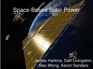
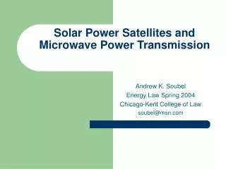
Wireless Power Transmission Optionsfor Space Solar Power IAC-02-r4.08 Henley, M.W. (1), Potter, S. D. (1), Howell, J. (2), and Mankins, J.C. (3) (1) The Boeing Company, (2) NASA Marshall Space Flight Center, (3) NASA Headquarters World Space Congress Houston, Texas October 17, 2002
Wireless Power Transmission Optionsfor Space Solar Power • Far Term Space Systems to beam power to Earth • Radio-Wave WPT System • Light-Wave Systems • Near term Technology Flight Demonstrations • Model System Concept 1A: 100 kWe satellite • Model System Concept 1B: 10 kWe lunar system
Global Power Consumption Remote Sensing of Current Global Power Consumption:A Composite Satellite Photograph of the Earth at Night
Initial Photovoltaic / Microwave SPSGEO Sun Tower Conceptual Design • “Sun-Tower” Design based on NASA Fresh Look Study • Transmitter Diameter: 500 meters • Vertical “Backbone” Length: 15.3 km (gravity gradient) • Identical Satellite Elements: 355 segments (solar arrays) • Autonomous Segment Ops: 1) Solar Electric Propulsion from Low Earth Orbit2) System Assembly in Gesostationary orbit • Large Rectenna Receivers: Power production on Earth
Photovoltaic / Laser-Photovoltaic SPSGEO Sun Tower-Like Concept Lasers and Optics 8 Ion Thrusters Solar Panel Segment Dimensions: 260 m x 36 m PMAD Avionics • Full Sun Tower Portion • 1530 modules • 55 km long • Backbone can be eliminated Deployable Radiator Multiple beams
Synergy Between Sunlight and Laser-PV WPTfor Terrestrial Photo-Voltaic Power Production • Large photo-voltaic (PV) power plants in Earth’s major deserts (Mojave, Sahara, Gobi, etc.) receive & convert light from 2 sources: 1) Directly from the Sun, and 2) Via WPT from SSP systems • Laser light is transmitted and converted more efficiently than sun-light • Wavelength is selected for good atmospheric transmissivity • Efficient Light Emitting Diode wavelengths match common PV band-gaps • Gravity gradient-stabilized SPSs are in peak insolation at ~6 AM and ~6 PM, with shadowing or cosine loss at mid-day and midnight • Heavy, complex gimbaled arrays add little extra power at these times • Both sides of rigid (not gimbaled) solar arrays can be light-sensitive • Back-side produces less power due to occlusion by wires • Translucent substrate (e.g., Kapton) also reduces back-side power levels • Even gimbaled arrays suffer a loss of power around noon and midnight • The combination of ambient sunlight plus laser illumination combines, at the terrestrial PV array, to match the daily electricity demand pattern
1.2 1.0 0.8 0.6 Normalized Power / Area 0.4 0.2 0.0 0 6 12 18 24 Time (Hours) Sunlight + Laser-PV WPT = ~ Power RequirementPhoto-Voltaic (PV) Power Station Receives Both PV Power from Sunlight PV Power from WPT-Light Total Power at PV Receiver 1.2 1.0 0.8 + = Normalized Power / Area 0.6 0.4 0.2 0.0 6 12 18 24/0 6 12 18 24 0 6 12 18 24/0 Time (Hours) Time (Hours) Time (Hours) Electrical Power Demand Normalized Output from SPS (Non-Tracking Arrays) Normalized Output from Sun Normalized Total Output Typical Electricity Demand 14
Area of Significant Concern Intermediate Area Area of Significant Benefit WPT Wavelength Trade for SSP
MSC-1A: Near Term Demonstration100 kWe Power Plug Satellite • Power System derived from existing ISS IEA (Integrated Energy Assembly) • IEA is successfully deployed in orbit now • IEA includes energy storage (batteries) • Current ISS array pair produces 61.5 kWe • Advanced PV cells can double IEA power • ~120 kWe with derivative array • MSC-1 demonstrates solar-powered WPT • Efficient power generation • Light Emitting Diodes (LEDs) achieve >30% conversion efficiency • ~36 kW transmitted in light beam • Effective heat dissipation via IEA radiators • Accurate pointing of beam via reflector 70.8 m 11.7 m
ISS with IEA Solar Panels Fully DeployedCurrent flight experience with large IEA reduces risk for near-term derivative applications
MSC-1A: Lunar and Mars Power (LAMP) ApplicationLaser WPT to Photo-Voltaics on the moon or Mars
MSC 1B: Lunar Polar Science Applications • Technology for Laser-Photo-Voltaic Wireless Power Transmission (Laser-PV WPT) is being developed for lunar polar applications by Boeing and NASA Marshall Space Flight Center • A lunar polar mission could demonstrate and validate Laser-PV WPT and other SSP technologies, while enabling access to cold, permanently shadowed craters that are believed to contain ice • Craters may hold frozen water and other volatiles deposited over billions of years, recording prior impact events on the moon (& Earth) • A photo-voltaic-powered rover could use sunlight, when available, and laser light, when required, to explore a large area of polar terrain • The National Research Council recently found that a mission to the moon’s South Pole-Aitkin Basin should be a high priority for Space Science • See paper IAC-02-r4.04, Space Solar Power Technology Demonstration for Lunar Polar Applications, for further details
North Pole (SEE BELOW) Moon’s Orbit • Sun Rays are Horizontal • at North & South Poles • NEVER shine into Craters • ALWAYS shine on Mountain South Pole (SEE BELOW) Solar Power Generation on Mountaintop Direct Communication Link Wireless Power Transmission for Rover Operations in Shadowed Craters Space Solar Power Technology Demonstration For Lunar Polar Applications • POSSIBLE ICE DEPOSITS • Craters are COLD: -300F (-200C) • Frost/Snow after Lunar Impacts • Good for Future Human Uses • Good for Rocket Propellants
Summary • Farther-term micro-wave WPT options are efficient, and can beam power through clouds / light rain, but require large sizes for long distance WPT and a specialized receiver (“rectenna”). • Nearer-term Laser-Photovoltaic WPT options are less efficient, but allow synergistic use of the same photo-voltaic receiver for both terrestrial solar power and SSP. • The smaller aperture size also allows smaller (lower cost) initial systems. • Laser-Photovoltaic WPT systems open new SSP architecture options. • Gravity gradient-stabilized “Sun Tower” SSP satellites may make more sense for laser systems than than for microwave systems, because the receiver also converts sunlight into electricity, to correct for the cosine loss otherwise observed in power production at mid-day. • Technology flight demonstrations can enable advanced space science and exploration in the near term. • “Power Plug” or “LAMP” spacecraft and Lunar Polar Solar Power outpost advance technology for far-term commercial SSP systems, while providing significant value for near-term applications.