Download
1 / 4
60 likes | 322 Vues
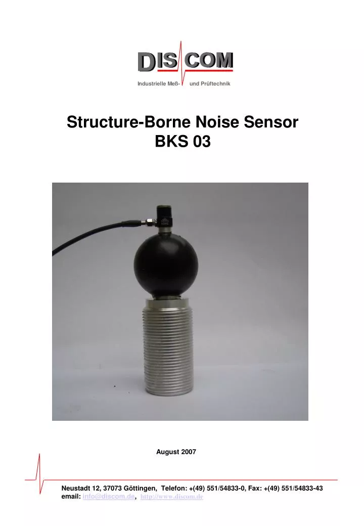
Structure- B orne N oise S ensor BKS 03. August 2007. Neustadt 12, 37073 Göttingen, Telefon: +(49) 551/54833-0, Fax: +(49) 551/54833-43 email: info@discom.de , http://www.discom.de. Construction Basics The BKS03 uses the MMF charge sensor KS 91D, which has a sensivity of 2.4pC/g.

E N D
Structure-Borne Noise Sensor BKS 03 August 2007 Neustadt 12, 37073 Göttingen, Telefon: +(49) 551/54833-0, Fax: +(49) 551/54833-43 email: info@discom.de, http://www.discom.de
Construction Basics The BKS03 uses the MMF charge sensor KS 91D, which has a sensivity of 2.4pC/g. The MMF ICP sensor KS 91E may also be used. It has a sensivity of 3.1 mV/g and needs no additional charge amplifier. Alternatively the B&K charge sensor 4393 may be used, which has a sensitivity of 3.1 pC/g. All these sensors weigh only 1,7 g and responds to frequencies up to 16.5 kHz. The sensor is mounted on a silicon ball, the top of it´s casing contacting the unit under test. A small steel plate is attached to the device and electrically isolated to prevent malfunction. Because of the small weight, the relatively large contact area, and the absorption of vibration by the rubber ball, resonance remains at a minimum. For the two figures below the transfer function of the Discom sensor and the transfer function of reference sensor were subtracted. Both sensors measured the structure-borne noise within a gear box. For figure A the Discom sensor was applied to the reference sensor, thereby ensuring that both sensors measure the same signal. For figure B the Discom sensor was applied to the gear box approximately 2cm from the reference sensor. Figure A exhibits almost linear transfer, both sensors being fed the same signal. Figure B is necessarily less perfect, because the difference actually measured owes in part to the varying signal at the two points on the gear box. Nevertheless no typical resonance frequencies were measured. Fig. A. Deviation of transfer function of Discom-sensor to transfer-function of reference sensor. Discom sensor applied directly to reference sensor. Function shows no resonance frequencies. Fig. B. Deviation of transfer function of Discom sensor to transfer function of reference sensor. Discom sensor applied to a point on the gear box a short distance from the reference sensor. Function shows no resonance frequencies.
Technical Data BKS03 • Sensitivity: • KS91D ~2.4 pC/g • KS91E ~3.1 mV/g • B&K4393 ~3.1 pC/g • Upper frequency limit: approx. 8 kHz • Can be connected to Rotassystems equipped with: • KS91E directly supplied with ICP • KS91D and B&K4393 with PCB or EndevcoICPcharge amplifiers. • Minimum resonance due to small weight of 1.7 g and resonance absorption by silicon ball. • Adapts to uneven surfaces. • Tightening moment of all sensors: • min. 0,3 Nm max. 1 Nm • Axial force on sensor: • min. 0,75Kp - max. 1,5kp • Preload of sensor on the device body: • min. 1,5 mm - max. 3mm