Download
1 / 22
220 likes | 317 Vues
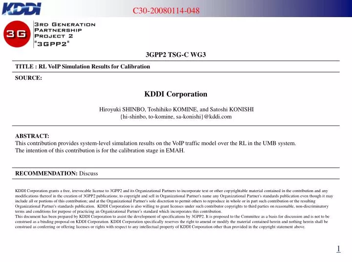
Simulation Setup. RL VoIP simulation All the parameters and methods for the simulations follow both the parameter spread sheet in C30-20080114-029 and the output metrics spread sheet in C30-20080114-021 P-ODCH Tx Power distribution is NOT included. (update soon) Notes:

E N D
Simulation Setup • RL VoIP simulation • All the parameters and methods for the simulations follow both the parameter spread sheet in C30-20080114-029 and the output metrics spread sheet in C30-20080114-021 • P-ODCH Tx Power distribution is NOT included. (update soon) • Notes: • Effective SNR AWGN curves (C30-20080114-029) is used. (Note that the PER curves for 1 tiles are used.) • AWGN channel and ITU Model (Ped-B and Veh-A) as the channel model • BRCH for F-DCH • AT Layout: C30-20080114-030 (Newly updated by QCOM) • Parameters: C30-20080114-019 • Scheduler: in line with the pseudo code in C30-20071025-006 • Transmission Deadline (at BS) of 100ms • Bin width for the statistics in the following figures • Throughput: 10kbps, Geometry: 0.25dB, PER: 0.01 • Note: the value in the x-axis represents the central value in a bin
Ped-B 3km/h channel • Aggregate sector throughput (Optional)
Ped-B 3km/h channel • PER distribution
Ped-B 3km/h channel • HARQ statistics (distribution)
Ped-B 3km/h channel • IoT CDF of RL OFDM traffic per Antenna
Ped-B 3km/h channel • 98% VoIP packet latency CDF
Ped-B 3km/h channel • Load (Tile occupancy) CDF
Ped-B 3km/h channel • RoT CDF of RL CDMA control per antenna
Ped-B 3km/h channel • CDF of AT VoIP packet jitter (Optional)Note: This graph is made from the average jitter of AT.
Veh-A 120km/h channel • Aggregate sector throughput (Optional)
Veh-A 120km/h channel • PER distribution
Veh-A 120km/h channel • HARQ statistics (distribution)
Veh-A 120km/h channel • IoT CDF of RL OFDM traffic per Antenna
Veh-A 120km/h channel • 98% VoIP packet latency CDF
Veh-A 120km/h channel • Load (Tile occupancy) CDF
Veh-A 120km/h channel • RoT CDF of RL CDMA control per antenna
Veh-A 120km/h channel • CDF of AT VoIP packet jitter (Optional)Note: This graph is made from the average jitter of AT.
Appendix ~ Output Metrics Spread Sheets ~ • Ped-B 3km/h channel • Veh-A 120km/h channel