Download
1 / 39
390 likes | 565 Vues
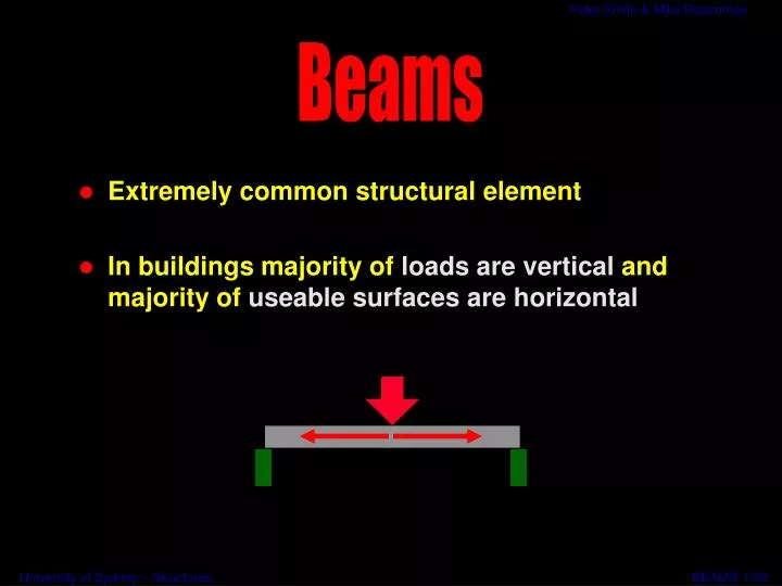
Beams. Extremely common structural element In buildings majority of loads are vertical and majority of useable surfaces are horizontal. 1/39. devices for transferring vertical loads horizontally. Beams. action of beams involves combination of bending and shear. 2/39.

E N D
Beams • Extremely common structural element • In buildings majority of loads are vertical and majority of useable surfaces are horizontal 1/39
devices for transferring vertical loads horizontally Beams action of beams involves combination of bending and shear 2/39
What Beams have to Do • Be strong enough for the loads • Not deflect too much • Suit the building for size, material, finish, fixing etc 3/39
Checking a Beam • what we are trying to check (test) • stability - will not fall over • adequatestrength - will not break • adequatefunctionality - will not deflect too much • what do we need to know • span - how supported • loads on the beam • material, shape & dimensions of beam • allowable strength & allowable deflection 4/39
? ? Designing a Beam • what we are trying to do • determine shape & dimensions • what do we need to know • span - how supported • loads on the beam • material • allowable strength & allowable deflection 5/39
Tributary Areas • A beam picks up the load halfway to its neighbours • Each member also carries its own weight this beam supports the load that comes from this area span spacing 6/39
Tributary Areas (Cont. 1) • A column generally picks up load from halfway to its neighbours • It also carries the load that comes from the floors above 7/39
Length Thickness Load = Surface area x Wt per sq m, or volume x wt per cu m Height Dead Loads on Elements • Code values per cubic metre or square metre • Multiply by the volume or area supported 8/39
Live Loads on Elements • Code values per square metre • Multiply by the area supported Area carried by one beam Total Load =area x (Live load + Dead load) per sq m +self weight 9/39
Distributed Load Point Load Reactions Loads on Beams • Point loads, from concentrated loads or other beams • Distributed loads, from anything continuous 10/39
Bending Shear What the Loads Do • The loads (& reactions) bend the beam, and try to shearthrough it 11/39
e e e e C T Bending Shear What the Loads Do (cont.) 12/39
beams in building designed for bending checked for shear Designing Beams • in architectural structures, bending moment more important • importance increases as span increases • short span structures with heavy loads, shear dominant • e.g. pin connecting engine parts 13/39
How we Quantify the Effects • First, find ALL the forces (loads and reactions) • Make the beam into a freebody (cut it out and artificially support it) • Find the reactions, using the conditions of equilibrium 14/39
W vertical reaction, R = W and moment reaction MR = - WL MR= -WL L R = W Example 1 - Cantilever Beam Point Load at End • Consider cantilever beam with point load on end • Use the freebody idea to isolate part of the beam • Add in forces required for equilibrium 15/39
W M = -Wx x V = W V = W Shear Force Diagram BM = Wx BM = WL Bending Moment Diagram Example 1 - Cantilever Beam Point Load at End (cont1.) Take section anywhere at distance, x from end Add in forces, V = W and moment M = - Wx Shear V = W constant along length (X = 0 -> L) Bending Moment BM = W.x when x = L BM = WL when x = 0 BM = 0 16/39
w /unit length L Total Load W = w.L MR = -WL/2 = -wL2/2 L/2 L/2 R = W = wL Example 2 - Cantilever Beam Uniformly Distributed Load Formaximum shear V and bending moment BM vertical reaction,R = W = wL and moment reactionMR = - WL/2 = - wL2/2 17/39
wx M = -wx2/2 X/2 X/2 V = wx V = wL = W Shear Force Diagram BM = wx /2 2 BM = wL2/2 = WL/2 Bending Moment Diagram Example 2 - Cantilever Beam Uniformly Distributed Load (cont.) For distributed V and BM Take section anywhere at distance, x from end Add in forces,V = w.xand momentM = - wx.x/2 ShearV = wx when x = LV = W = wL when x = 0V = 0 Bending MomentBM = w.x2/2 when x = LBM = wL2/2 = WL/2 when x = 0BM = 0 (parabolic) 18/39
“Positive” shear “Negative” shear R.H down L.H down L.H up R.H up Sign Conventions Shear Force Diagrams • To plot a diagram, we need a sign convention • The opposite convention is equally valid, but this one is common • There is no difference in effect between positive and negative shear forces 19/39
W3 W1 W2 R1 Diagram of loading R2 W1 R1 W2 R2 W3 Shear Force Diagram Plotting the Shear Force Diagram • Starting at the left hand end, imitate each force you meet (up or down) 2039
Shape of the Shear Force Diagram • Point loads produce a block diagram • Uniformly distributed loads produce triangular diagrams Diagrams of loading Shear force diagrams 21/39
Split in timber beam Reo in concrete beam What Shear Force does to the Beam • Although the shear forces are vertical, shear stresses are both horizontal and vertical • Timber may split horizontally along the grain • Shear is seldom critical for steel • Concrete needs • special shear reinforcement • (45o or stirrups) 22/39
Hogging NEGATIVE Sagging POSITIVE - + Sign Conventions Bending Moment Diagrams • To plot a diagram, we need a sign convention • This convention is almost universally agreed 23/39
Saggingbending momentisPOSITIVE (happy) + Hoggingbending momentisNEGATIVE (sad) - Sign Conventions Bending Moment Diagrams (cont.) 24/39
Cantilevers produce negative moments - - Cantilevers • Simple beams produce positive moments - - + + Simple beam Built-in beam • Built-in & continuous beams have both, with negative over the supports Positive and Negative Moments 25/39
+ + This way mimics the beam’s deflection This way is normal coordinate geometry Where to Draw the Bending Moment Diagram • Positive moments are drawn downwards (textbooks are divided about this) 26/39
Diagrams of loading Bending moment diagrams Shape of the Bending Moment Diagram • Point loads produce triangular diagrams 27/39
UDL UDL Diagrams of loading Bending moment diagrams Shape of the Bending Moment Diagram (cont1.) • Distributed loads produceparabolic diagrams 28/39
Maximum value Shape of the Bending Moment Diagram (cont.2) • We are mainly concerned with the maximum values 29/39
- - - - + + + Shape of the Bending Moment Diagram (cont.3) • Draw theDeflected Shape(exaggerate) • Use the Deflected shape as a guide to where the sagging (+) and hogging (-) moments are 30/39
Simply supported Continuous Can we Reduce the Maximum BM Values? • Cantilevered ends reduce the positive bending moment • Built-in and continuous beams also have lower maximum BMs and less deflection 31/39
Total load = W W (w per metre length) L L Central point load Max bending moment = WL/4 Uniformly distributed load Max bending moment = WL/8 or wL2/8 where W = wL Standard BM Coefficients Simply Supported Beams • Use the standard formulas where you can 32/39
Total load = W W (w per metre length) L L End point load Max bending moment = -WL Uniformly Distributed Load Max bending moment = -WL/2 or -wL2/2 where W = wL Standard BM Coefficients Cantilevers 33/39
W W W /m W W W W W W W W W /m W W Standard BM Coefficients Simple Beams Beam Cable BMD 34/39
W W W = wL W = wL L L L L V = +W/2 V = +W/2 V = +W V = +W V = -W/2 V = -W/2 Mmax = WL/8 = wL2/8 Mmax = -WL Mmax = -WL/2 = -wL2/2 Mmax = WL/4 SFD & BMD Simply Supported Beams 35/39
How much compressive stress? How much tensile stress? How much deflection? What the Bending Moment does to the Beam • Causes compression on one face and tension on the other • Causes the beam to deflect 34/37
how big & what shape? How to Calculate the Bending Stress • It depends on the beam cross-section • We need some particular properties of the section is the section we are using as a beam 37/39
What to do with the Bending Stress • Codes give maximum allowable stresses • Timber, depending on grade, can take 5 to 20 MPa • Steel can take around 165 MPa • Use of Codes comes later in the course 38/39
we need to find the Section Properties Finding Section Properties next lecture 39/39