Download
1 / 26
270 likes | 508 Vues
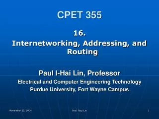
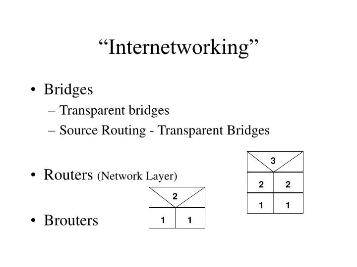
“Internetworking”. Bridges Transparent bridges Source Routing - Transparent Bridges Routers (Network Layer) Brouters. 3. 2. 2. 2. 1. 1. 1. 1. Why Bridges. Isolation of Physical Layer Effects Bandwidth Multiplication Security or Traffic Isolation. File server. Workstations.

E N D
“Internetworking” • Bridges • Transparent bridges • Source Routing - Transparent Bridges • Routers (Network Layer) • Brouters 3 2 2 2 1 1 1 1
Why Bridges • Isolation of Physical Layer Effects • Bandwidth Multiplication • Security or Traffic Isolation
File server Workstations LAN traffic Bridge LAN traffic Terminal server Host Terminals Segmenting Traffic
Transparent Bridges • Interconnect multiple cable segments to allow for extension of a network. • Can be used to interconnect different access methods (Ethernet to Token Ring) and different physical layers. • Operate at the data link layer. • They are protocol transparent. • They are designed to operate regardless of the upper-layer protocol. • They operate on the source and destination address in the MAC header.
T-L-F Bridges • Bridges only forward traffic destined for other cable segments. • They operate transparently to any stations that are active on the network. • Packet formats and software drivers on the workstations remain the same. • Bridges do not have to be programmed with the addresses of all the devices on the network.
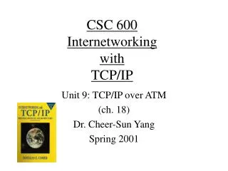
Node D Node F Terminals Node C Cable segment 1 Node C, D and F are on this cable segment through port 2. Port 2 Forwarding table Bridge Nodes A, B, and E are on this cable segment though port 1. Port 1 Cable segment 2 Node E Node A Node B Learning, Filtering, and Forwarding
Node B Node A Cable segment 2 Port ID 1 C 2 D 2 A 1 B 1 Fowarding Table Port ID 2 Filtered Cable segment 1 Packet transmitted Node C Node D Filtering - An Example
Node B Node A Cable segment 2 Forwarded Port ID 1 C 2 D 2 A 1 B 1 Forwarding table Port ID 2 Cable segment 1 Node C Node D Forwarding - An Example
Node B Node A Cable segment Z A B Bridge 1 C D Cable segment Y A B Bridge 2 Bridge table C D Cable segment X A B Bridge 3 C D Cable segment V Node C Node D Forwarding Beyond One Bridge
Loops • Complexity of bridging arises when two or more bridges interconnect the same two cable segments. • This is called providing redundancy or providing a loop. • There are problems with this type of design including: • duplicate packets, • broadcast packets, and • unknown destination packets.
Node B Node A Two packets received Cable segment 2 Bridge 1 Bridge 2 Cable segment 1 Single packet transmitted Node D Node C Duplicate Packets
Packet received and transmitted back by second bridge Node B Node A Cable segment 2 Loop Bridge 2 Bridge 1 Cable segment 1 Broadcast packet transmitted Node D Node C Broadcasts
Node A Node B Packet received and transmitted back by second bridge Cable segment 2 Loop Bridge 1 Bridge 2 Cable segment 1 Destination Z packet transmitted Node D Node C Unknown Destination Address
Spanning Tree Algorithm • Bridged networks must allow for redundancy. Only one path should be enabled to any destination on the network. • STA is a protocol unto itself. Don’t confuse it with the transparent bridge protocol. IEEE 802.1d • In an active STA topology certain bridges are allowed to forward packets. • Other bridges will participate in the STA but do not forward packets. • These are backup bridges that dynamically become available. • Bridges that do not forward packets are placed in blocking mode. • These bridges still participate in the spanning tree protocol.
Source Routing Bridges • Developed as a bridge protocol for Token Ring LANs. • Source routing gained popularity due to IBM’s support of it. • It is easy to install a source route network. • It is not easy to grow a source route network into a large network. • Invented due to technical limitations of the source route chip set.. Early source route chip sets could not be set for promiscuous mode. • Source routing was also invented to allow two non-routing protocols to be placed on a LAN: NetBIOS and SNA. • Source Routing does not build forwarding tables based on MAC addresses. • Most of the intelligence for this algorithm is found in the network stations. • Each frame carries complete route information with it.
Source Routing Features • Source routing requires split intelligence to be carried in the node and the bridge. • All frames contain routing information, which does produce more overhead. • Uses STA to configure which bridges will forward single route broadcast frames. • All paths are active which legally allows loops to be designed. • Provided a routing solution for those protocols that could not be routed (NetBIOS). • Easy to follow ring/MAC address for troubleshooting.
Source Routing Features (cont.) • Source Routing originated as an alternative to transparent bridging • Originally, Token Ring could not be placed in promiscuous mode ( requirement for transparent bridging) and therefore an alternative model was created • Allowed for SNA and NetBIOS traffic an attempt to enjoy the benefits of routing • As a data link layer implementation.
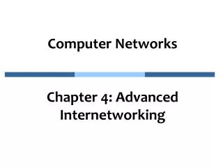
Source Routing Overview • Each separate ring is assigned a unique ring number, assigned on the source route bridge port and not on the ring station. • Each bridge is assigned a bridge number. There is a single number for the whole bridge, no matter how many ports it has. • End stations try to find destination ring stations by broadcasting special discovery frames. • A frame will contain source route information based on one bit in the source address. • A source route frame may not cross more than seven bridges. • At the eighth bridge, the frame is discarded.
Source Routing Example MAU MAU 2 Find a station off ring Bridge 5 Node 2 Node 1 Bridge 6 1 Find a station on the local ring Bridge 7 Ring 4 Ring 3
Routing Information Indicator (RII) Optional Routing Information Field Source Service Access Protocol (SSAP) Destination Service Access Protocol (DSAP) Source Address Starting Delimiter Access Control Frame Control Destination Address Rest of Token Ring frame Up to 8 RD fields 2 bytes Routing Control Route Designator Route Designator . . . . . . Bridge number Ring number B B B L L L L L D F F F r r r r 12 bits 4 bits 1 - F bridge IDs 1 - 4095 rings Routing Information Field
The Route Designator Bridge 1 Discovery frame Ring B Ring A RC RC RD1 RD2 Token Frame Header Token Frame Trailer Token Frame Header Token Frame Trailer Routing Control Routing Control 00B1 00A0 Routing Information Field Routing Information Field
Source Route Frame Types • Four types of Source Route frames: • Single Route Explorer (SRE) • Also known as Spanning Tree Explorers (STE) • So named by the IEEE 802.5 working group • All Routes Explorer (ARE) • Specifically Routed Frame (SRF) • Single Route Explorer with a specific route return.
Copy and bit reverse Token Ring frame SNAP header AC OUI SD FC DA SA RIF DSAP SSAP CTRL Type Info FCS ED FS Discard Copy Ethernet frame Preamble DA SA Type Info FCS Token Ring to Ethernet Conversion
Ethernet to Token Ring Conversion Copy and bit reverse Ethernet frame FCS Type Preamble DA SA Info Copy SD AC FC DA SA RIF DSAP SSAP CTRL Type Info FCS ED FS OUI Insert SNAP header Token Ring frame
Copy and bit reverse Token Ring frame SD AC FC DA SA RIF DSAP SSAP CTRL ED FS Info FCS Cut Insert Copy Length Info PAD FCS Preamble SFD DA SA DSAP CTRL SSAP IEEE 802.3 frame Token Ring to IEEE 802.3 Conversion
IEEE 802.3 to Token Ring Conversion Copy and bit reverse IEEE 802.3 frame FCS Length PAD Preamble SFD DA SA SSAP DSAP Info CTRL Cut Insert Copy SD AC FC DA SA RIF DSAP SSAP CTRL FS ED Info FCS Token Ring frame