Download
1 / 7
80 likes | 435 Vues
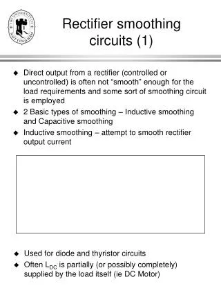
Rectifier smoothing circuits (1). Direct output from a rectifier (controlled or uncontrolled) is often not “smooth” enough for the load requirements and some sort of smoothing circuit is employed 2 Basic types of smoothing – Inductive smoothing and Capacitive smoothing

E N D
Rectifier smoothing circuits (1) • Direct output from a rectifier (controlled or uncontrolled) is often not “smooth” enough for the load requirements and some sort of smoothing circuit is employed • 2 Basic types of smoothing – Inductive smoothing and Capacitive smoothing • Inductive smoothing – attempt to smooth rectifier output current • Used for diode and thyristor circuits • Often LDC is partially (or possibly completely) supplied by the load itself (ie DC Motor)
Rectifier smoothing circuits (2) • Capacitive smoothing – attempt to smooth rectifier output voltage • Only used with diode circuits • Extensively used as the “front end” to provide the DC link (DC supply) needed for PWM inverter variable speed drive systems (see later in module), often LC version (next page) is used at higher powers
Rectifier smoothing circuits (3) • A combination of Capacitive and Inductive (LC) smoothing is sometimes used for diode circuits • Operates like inductive smoothing if rectifier output current is continuous • Operates like capacitive smoothing if rectifier output current is discontinuous (ie has intervals where it = 0) • Analysis of all smoothing circuits depends on whether rectifier output current is continuous or discontinuous • Discontinuous – capacitive (usually), Inductive at very low output currents, L-C at low output currents • Continuous – inductive at normal output currents, LC at high output currents
Inductive Smoothing- continuous current • Waveforms – see handout • Analysis method to find I for a given L or vice versa • Assume VL is smooth • Use mean value of ID to determine VXY waveform (ie and ) • VL = mean value of VXY (mean voltage across inductor = 0) • Draw VXY on template and superimpose VL • Determine whether VL crosses VXY above or below the overlap part of the waveform • Calculate the easier of the two areas (above or below VL) and use I = voltage-time area/L • If VL happens to cross through the overlap part of VXY then neglect the smaller of the two little “triangular” areas formed • If the inductor has a resistance R – then use the approximation VL + Id(mean) *R = mean of VXY • See worked example (to be handed out)
Inductive Smoothing- discontinuous current • If the mean value of Id is progressively reduced (due to changing load for example), the ripple in Id means that it will eventually touch 0 (before the mean value gets to zero) and all the devices in the rectifier will turn off • The current will stay at zero until another pair of devices is forward biassed (diode circuit) or another pair of devices is fired (thyristor circuit) • This is discontinuous current operation – see handout for waveforms • Things to note: • There is no overlap • Each thyristor must be fired twice (once at the normal place and again 60O later) to get proper operation if the current is discontinuous – otherwise we will never get a current path • The expression for VXY(mean) derived before no longer holds – VXY(mean) is bigger than this • VXY(mean) depends strongly on the load current – rectifier has considerable regulation in this mode – can cause control problems – see H5CEDR • Can be analysed like capacitive smoothing (see later) for the diode case – more difficult for thyristor case in general
Capacitive Smoothing • See handout for waveforms • Current normally discontinuous unless extra AC side inductance is added and current is high – we will assume discontinuous current • For analysis – assume capacitor voltage is smooth – see handout • Things to note: • There is no overlap • Supply current has very high harmonic distortion – distortion factor is poor (displacement factor is OK) – hence power factor is poor • Power factor can be improved by adding AC side inductance to make pulses of current broader and lower • Poor power quality aspects of this circuit are making it increasingly unacceptable – but it is still used in very large numbers
LC Smoothing • If current is continuous – analyse exactly as inductive smoothing • If current is discontinuous – analyse as capacitive smoothing • Remember to add the DC side inductance in the equation for calculating the peak current