Download
1 / 58
580 likes | 682 Vues
Laboratories and Materials Teaching Hardware-Software Co-Design. D.G. Beetner and H.J. Pottinger Electrical and Computer Engineering University of Missouri-Rolla. Outline. Background and Motivation Overview Introductory Example Laboratory Exercises Detailed Example Evaluation.

E N D
Laboratories and Materials Teaching Hardware-Software Co-Design D.G. Beetner and H.J. Pottinger Electrical and Computer Engineering University of Missouri-Rolla
Outline • Background and Motivation • Overview • Introductory Example • Laboratory Exercises • Detailed Example • Evaluation
Background • Hardware and software developed separately in past • Increasingly risky • Systems on a Chip • Short market windows • Difficult to partition hardware and software • Co-Design reduces number of prototypes and time-to-market • Rapidly growing demand
Background • Hardware-Software Co-design fundamental to digital systems design • Undergraduates in CpE, EE, and CS should be introduced to this concept • Developed software and laboratories which introduce Co-design at the junior level
Laboratory Objective • Teach concepts of microcontrollers and hardware-software co-design • Hardware-Software partitioning • Re-use of intellectual property (IP) • Hardware-Software co-simulation • Embedded software in C and ASM • Communication with external devices • Real-time systems
Course Design • Associated course • Junior level • Focused on 8051 microcontroller • Mix of CpE, EE, and CS students • Lab is not required • Student background • C++ • Electronic design automation tools • Rapid prototyping with FPGAs
Experiment Outline • Develop and simulate software • Develop and simulate hardware • Co-simulate hardware and software • Verify design in hardware
Laboratory Equipment • Keil Software Development Tools • C and ASM • 8051 software simulation • Free evaluation software
Laboratory Equipment • Mentor Graphics design automation tools • 8051 simulation model • Clock-cycle accurate • Executes compiler-generated code • Complete functionality
Laboratory Equipment • Mentor Graphics design automation tools • 8051 simulation model • Clock-cycle accurate • Executes compiler-generated code • Complete functionality
Laboratory Equipment • XS40 board by Xess corporation • 8031 microcontroller • Xilinx FPGA • VGA port • 7-segment LED • Generous pin-probe points
Experiments • Several labs developed • Introduction to Hardware-Software Co-Simulation • Hardware-Software Co-Verification • Extending the 8051 with External Hardware • Design with intellectual property: Creating a VGA display • Bi-directional serial communication with interrupts
Projects • Digital LCD alarm clock • Virtual pet • MP3 player controller • “Pong” game • Automatic pet feeder • Simon game
Introductory Example: 7SegDisp • Objectives: • Instructor’s overview of: • 8051 model usage • Co-verification methodology • Extension to exclusive VHDL approach • Implement: • 8051 address latch • Seven segment display output port
7SegDisp Overview • Similar to UMR Lab Exercise #4 • A collage of labs 1, 4, and 5 • Construct an eight bit latch for use as: • Address latch for 8051 expanded mode • Output port for seven segment display on XS40 • Construct an address decoder for output port at 0x7F55 • Interface to XS40 starting frame model • Write and test C program to display message • Simulate entire system and test on XS40 hardware
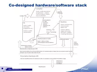
A(15:0) P2 A D A15 CS P0 D OE PSEN Q Sram ALE G P0 D Latch8 Q PSEN =7F55H G WRn Display Latch8 Decoder 8051 FPGA Block Diagram of 7SegDisp
7SegDisp Specifications • Must execute 8051 code from XS40 Sram • Sram is 32k bytes from 0x0000 to 0x7FFF • Latch data for seven segment display • Display port in xdata at address 0x7F55 • Software to display “0123456789” continuously at one second intervals
Lab Sequence Overview • Eight bit latch design • Intro to H/W S/W Co-simulation • Hardware verification of Gnome S/W • Extending the 8051 • Single chip memory spaces for 8051 • Design with IP – a VGA controller • Bidirectional Serial I/O using interrupts
Ex 1: Eight Bit Latch Design • 8-bit parallel port using an FPGA • Re-familiarize with Design Architect • Simulate hardware with Quicksim • Familiarization with XS40 board • Use a PC to provide stimulus to hardware • Compare hardware and simulation model response
Ex 2: Intro to Co-simulation • Write assembly program to multiply two 4-bit numbers • Hand assemble and create Intel hex file • Verify using a hardware model • Illustrate importance of simulation • Currently using Xess’ GNOME processor
Ex 3: Hardware Verification • Familiarization with XS40 Board • Tradeoffs between simulation and hardware testing • Use of oscilloscope and logic analyzer • ‘Fix’ unexpected change in hardware • Infer internal behavior by observing external signals
Ex 4: Extending the 8051 • Add address latch and external output port • Improve hardware-software design skills • Demultiplex 8051 address/data bus • Observe timing of 8051 bus signals • Introduce 8051 simulation model • More familiarization with XS40 board
Ex 5: Single Chip Memory Spaces • Implement xdata and code space in SRAM • Xdata at 0x5000 • Code at 0x0000 • Write message display program in assembly language • Use of software development tools • Illustrate importance of hardware/software co-verification • Students write software and make small modification to previous hardware design
Ex 6: Design with IP • Develop interface to a VGA controller soft macro • VGA core implements 16 x 8 character display • Write message display program in C for 8051 • Reinforces importance of co-verification • VGA core is a ‘non-standard’ 8051 peripheral • Need to verify both HW and SW operating together
Ex 7: Serial Communication • Bi-directional comm with two serial ports • Design system that can communicate with another group’s XS40 board • Use interrupts to service serial port • Design re-use (modification of lab 6) • Re-inforce co-verification techniques • Improve C programming skills
Specification Edit Compile Debug Capture Simulate Integrate Hardware and Software Place and Route HW-SW Co-design Process Hardware Verification
Keil vision: • IDE • C51 • dScope Specification Edit Compile Debug Capture Simulate Integrate Hardware and Software Place and Route HW-SW Co-design Process Hardware Verification
Mentor: • Design Arch • Quicksim Specification Edit Compile Debug Capture Simulate Integrate Hardware and Software Place and Route HW-SW Co-design Process Hardware Verification
Specification Edit Compile Debug Capture Simulate Integrate Hardware and Software Place and Route HW-SW Co-design Process Hardware Verification QuicksimPro: • Quicksim & • Modeltech
Specification Edit Compile Debug Capture Simulate Integrate Hardware and Software Place and Route HW-SW Co-design Process Hardware Verification Xilinx Alliance
Hello World Program Specification: Display each char of message for two seconds With a one second pause in between Seven segment display port at 0x7f55 Bit 0 is segment a, bit 6 is segment g #define SEG7 XBYTE[0x7F55] void main (){ static code char msgtxt[]= "0123456789"; char code *cptr; TMOD=0x01; /* 16bit timer mode */ while (1) { cptr= msgtxt; while(*cptr){ SEG7= decode(*cptr++); // pause between characters #ifndef SIMULATION delay(2); SEG7= 0; delay(1); #endif } /* while (*cptr) */ } /* while(1) */ } Get next char Lookup segment values Pause if not simulating no Done?
Lab 4 Starting Frame • Archive file with simulation model etc. • XS40 schematic model • 8051 model • 32k sram model • Clock, seven segment display, etc models • XC4005 FPGA starting frame • Hello world hex object file: hello.hex • Results of previous lab: eight bit latch
8051 Model • 8051 Schematic symbol is linked to an underlying VHDL behavioral model
Sram model (1) Sram wrapper Address map Sram symbol
Sram model (2) • SRAM model is a modified version of Andre Klindworth’s VHDL model
Address latch sample solutions Typical student solution The answer book!
Finished FPGA schematic model • Screen shot of finished xc4005
Linking program file to model • Closeup of file property, hello.hex, and dir listing
QSPro Simulator • Mixed Schematic and VHDL models • Gate level plus VHDL simulator • QSPro startup
QSPro Simulation Environment • Screenshot of A typical simulation setup
7SegDisp Write Cycle • Screen shot of cycle showing a write to 7f55
Lab Equipment • A picture of a typical lab setup
Comparison of Hardware and Simulation Results Simulation trace Scope trace