Download

1 / 26
260 likes | 408 Vues
MONALISA. Laser based alignment and stability monitoring. The Oxford MONALISA Group. MPhys alumnus. Armin Reichold. David Urner. Paul Coe. Matthew Warden. Geoffrey Rayner. Interferometer experience at Oxford built up since mid 1990s

E N D
MONALISA Laser based alignment and stability monitoring MONALISA : JAI Oxford MDI ATF2TILC08Sendai Japan
The Oxford MONALISA Group MPhys alumnus Armin Reichold David Urner Paul Coe Matthew Warden Geoffrey Rayner • Interferometer experience at Oxford • built up since mid 1990s • Interferometer based alignment is "coming of age" • Key results imminent from 3 interferometer groups • IWAA 08 presentations http://www-conf.kek.jp/iwaa08/ MONALISA : JAI Oxford MDI ATF2TILC08Sendai Japan
Interferometers: Best of old & new High precision in fundamental physics since 1887 • In 2008 we have • laser sources • fibre amplifiers • fibre coupling • Enabling • radiation tolerance • cost effective • scaleable • rapid read out MONALISA : JAI Oxford MDI ATF2TILC08Sendai Japan
The whole is greater than the sum of the parts Why 2008 is so exciting for us • MONALISA enjoying fruitful collaboration in Oxford: • LiCAS • Prototype rapid survey system (tests in DESY) • ATLAS: SCT optical alignment • being completed at CERN MONALISA : JAI Oxford MDI ATF2TILC08Sendai Japan
Beam based feedback • Is essential for ILC, CLIC • Requires an operational beam • prerequisite initial alignment • components move after survey • Working alignment needs to be maintained / restored • between trains • 200 ms is long enough for several 100 nm movement • after push-pull events: • IR hall floor will move after rolling two heavy detectors • after shutdown periods MONALISA : JAI Oxford MDI ATF2TILC08Sendai Japan
Component Alignment Challenge • relative mechanical DoF between many neighbouring components • choose important rotations / displacements • in-situ • hostile radiation environment • cramped spaces • ILC, CLIC require large dynamic range • (sub) nm precision over range of metres • micron precision over many 10s of metres MONALISA : JAI Oxford MDI ATF2TILC08Sendai Japan
MONALISA: Benefits 1 Monitoring fiducial locations on key components • after interruption of beam • independently follows changes in alignment • during commissioning / start up • improves understanding of machine behaviour • before accelerator operation • speeds up initial convergence of machine MONALISA : JAI Oxford MDI ATF2TILC08Sendai Japan
MONALISA: Benefits 2 Return detector / QDzero position after push-pull • expect to get micron repeatability • for return of magnet positions • get machine within beam based capture range • improves switchover time • more reliable accelerator operation • lower chance of damage • luminosity can only win MONALISA : JAI Oxford MDI ATF2TILC08Sendai Japan
MONALISA : Requirements • The ideal for any survey/monitor system • measure distances along clear lines of sight • use evacuated narrow tubes • MDI issues for detector LoI • issues broadly as discussed here at SENDAI in Tuesday MDI session • e.g. push pull vacuum connections MONALISA : JAI Oxford MDI ATF2TILC08Sendai Japan
Personal comments to add to Sendai meeting MDI discussion • QD zero in tunnel scenario very exciting • MONALISA (as other systems) • much simpler / cheaper • much easier to achieve target performance • Personal plea to consider it favourably • IMHO: • Achievable luminosity probably greater with simpler ILC MONALISA : JAI Oxford MDI ATF2TILC08Sendai Japan
MONALISA illustration • Returning to buried QDzero scenario • following sequence shows an ILC study • simulated example geometry • compact straightness monitor (CSM) • concept arises from necessity MONALISA : JAI Oxford MDI ATF2TILC08Sendai Japan
Solenoid return yoke Final Vertically Focussing Quadrupole Distance Meter Straightness Monitor Geometry Measure movement of QD0s with respect to some points radially outwards through detector field yoke Then must measure the relative motion of these end points Exact geometry to be determined in synch with detector design Detail for single QDzero MONALISA : JAI Oxford MDI ATF2TILC08Sendai Japan
Solenoid return yoke Straightness monitor concept Final Vertically Focussing Quadrupole Geometry Measure movement of QD0s with respect to some points radially outwards through detector field yoke Then must measure the relative motion of these end points Exact geometry to be determined in synch with detector design MONALISA : JAI Oxford MDI ATF2TILC08Sendai Japan
Solenoid return yoke Final Vertically Focussing Quadrupole Geometry Extension into tunnels possible. Allows monitoring of other magnets positions with respect to QD0 MONALISA : JAI Oxford MDI ATF2TILC08Sendai Japan
Absolute distance Displacement Measurement lines • We measure distances along measurement lines using two techniques: • Absolute distance interferometry • Displacement interferometry • Each line is the same, and is capable of performing both types of measurement. MONALISA : JAI Oxford MDI ATF2TILC08Sendai Japan
FSI: Frequency scanning Interferometry MONALISA : JAI Oxford MDI ATF2TILC08Sendai Japan
Intensity Interferometer operation MONALISA : JAI Oxford MDI ATF2TILC08Sendai Japan
ΔD = (c/2πν) ΔΦ D = (c/ 2π) (ΔΦ/Δnu) D = R (ΔΦ/Δθ) Fixed Frequency Interferometry Frequency Scanning Interferometry Interferometer operation Phase = 2π (Optical Path Distance) / Wavelength Φ = 2π D / λ = 2π D (ν / c) R = (c/ 2π) (Δθ/Δnu) MONALISA : JAI Oxford MDI ATF2TILC08Sendai Japan
Add box to reduce air turbulence s=750nm s=70nm FSI: recent results in air MHz raw signal Distance RMS < 1mm MONALISA : JAI Oxford MDI ATF2TILC08Sendai Japan
FFI: recent results in air Static resolution estimate Following displacements MHz raw signal Four fibres' raw signal 5 nm RMS Displacement MONALISA : JAI Oxford MDI ATF2TILC08Sendai Japan
Up coming work at Oxford • Have vacuum vessel ready for testing interferometers down to below 1 mbar • Frequency stabilised ultra-narrow linewidth laser will improve reliability of FFI displacement measurements MONALISA : JAI Oxford MDI ATF2TILC08Sendai Japan
Vacuum Vessel (0.1-1mbar) Equipped with 4 x 8 way fibre LID NOT SHOWN HERE! 800mm AFTER BEFORE MONALISA : JAI Oxford MDI ATF2TILC08Sendai Japan
Rb-87 frequency reference (FFI) • Target ~3 khz linewidth • Need 19 kHz for 1nm @ 10m Almost all equipment has been ordered or purchased : setting up from March on MONALISA : JAI Oxford MDI ATF2TILC08Sendai Japan
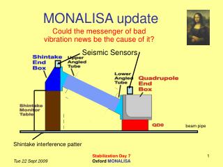
ATF2 extraction line: 08 Feb 2008 QD1 QD0 MONALISA : JAI Oxford MDI ATF2TILC08Sendai Japan
ATF2: Monitor relative vertical motion ATF2 beam direction QD0 Shintake table MONALISA : JAI Oxford MDI ATF2TILC08Sendai Japan
Summary • MONALISA will be a boon to ILC • QDzero nanometre vertical alignment • Repositioning after push-pull to microns • Needs to be included in MDI engineering and detector layout • push to get MONALISA concepts into detector • greatly encouraged by creative thinking at TILC08 • Performance demonstrations on going • Oxford: Vacuum and frequency reference systems • ATF2: Final focus monitoring system to be installed MONALISA : JAI Oxford MDI ATF2TILC08Sendai Japan