Download
1 / 8
80 likes | 86 Vues
Understanding the theory behind cycle design in the Dewar process for a high efficiency helium liquefaction system.

E N D
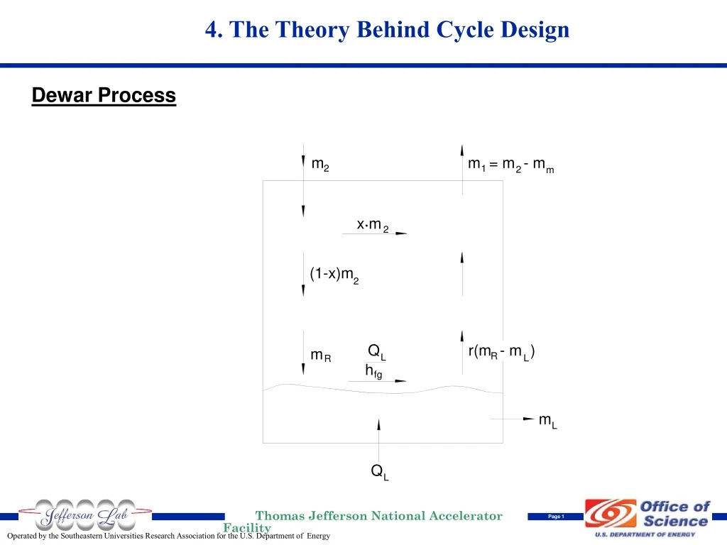
4. The Theory Behind Cycle Design Dewar Process
The Theory Behind Cycle Design (Cont.) Dewar Process
The Theory Behind Cycle Design (Cont.) Possible High Efficiency Helium Liquefaction System
In summary, the Carnot step was explained. For a given number of expansion stages, these Carnot steps (i.e., the temperature ratio) are the same for both refrigerator and liquefier, and result in the minimum compressor flow (and therefore the minimum input power). This is indirectly saying that the ideal placement of the expanders with respect to temperature for both refrigerator and liquefier are the same. Due to practical limitations, the system will likely operate at slightly different temperatures between the two modes, and also slightly away from the Carnot step. These limitations can be the fixed flow coefficients and efficiencies of the expanders and compressors, insufficient heat exchanger area or operating for a different optimal condition (e.g., at maximum system capacity rather than the minimum input power condition). The main difference between operating as a refrigerator vs. a liquefier in the configuration shown in Figure 4.3.2, is that the mass flow through each expander is approximately the same for a liquefier but not for the a refrigerator operating at the optimal minimum input power condition. In a refrigerator each Carnot step above the final cold expanders (i.e., above ~20K) is only required to handle the heat exchanger losses and heat leak. In contrast, in a liquefier all the expanders handle an approximately equal amount of compressor flow, and therefore an (approximately) equal amount of compressor isothermal compressor input power. The Theory Behind Cycle Design (Cont.)