Download
1 / 46
620 likes | 1.28k Vues
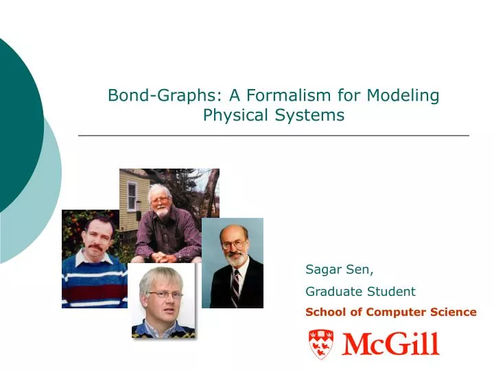
Bond-Graphs: A Formalism for Modeling Physical Systems. H.M. Paynter. Sagar Sen, Graduate Student School of Computer Science. The Ubiquity of Energy. Energy is the fundamental quantity that every physical system possess. Energy is the potential for change . System.

E N D
Bond-Graphs: A Formalism for Modeling Physical Systems H.M. Paynter Sagar Sen, Graduate Student School of Computer Science
The Ubiquity of Energy • Energy is the fundamental quantity that every physical system possess. • Energy is the potential for change. System Not So Energy Efficient (Falling) Major Heat Energy Loss Energy Efficient Eventually Back on your feet Free Energy (Useful Energy): DECREASES Since no inflow of free energy Heat Energy Released (Not so useful): INCREASES Total Energy=Free Energy + Other Forms of Energy ,is conserved Bond Graphs, (c) 2005 Sagar Sen
Bond Graphs: A Unifying Formalism Thermodynamic Mechanical Hydraulics Electrical Magnetic Why Bond-Graphs (BG)? Bond Graphs, (c) 2005 Sagar Sen
First Example: The RLC Circuit RLC Circuit Symbolic BG Standard BG i i i Bond Graphs, (c) 2005 Sagar Sen
Second Example: Damped Mass Spring System Damped Mass Spring System Symbolic BG Standard BG 1 v Bond Graphs, (c) 2005 Sagar Sen
Lets compare... • The Damper is analogous to the Resistor • The Spring is analogous to the Capacitor • The Mass is analogous to the Inductor • The Force is analogous to the voltage source • The Common Velocity is analogous to the Loop Current The Standard Bond-Graphs are pretty much Identical!!! Bond Graphs, (c) 2005 Sagar Sen
Common Bond Graph Elements Bond Graphs, (c) 2005 Sagar Sen
Closer Look at Bonds and Ports(1) Element 1 Element 2 Ports The energy flow along the bond has the physical dimension of power. These pairs of variables are called (power-) conjugated variables Bond Graphs, (c) 2005 Sagar Sen
Closer Look at Bonds and Ports(2) Two views for the interpretation of the bond • As an interaction of energy: The connected subsystems form a load to each other by the energy exchange. A physical quantity is exchanged over the power bond. • As a bilateral signal flow: Effort and Flow are flowing in opposite directions (determining the computational direction) Element 1 Element 2 Element 1 Element 2 e e Element 1 Element 2 Element 1 Element 2 f f Element1.e=Element2.e Element2.f=Element1.f Element2.e=Element1.e Element1.f=Element2.f Why is the power direction not shown? Bond Graphs, (c) 2005 Sagar Sen
Bond Graph Elements (1): Storage Elements (C-element) Storage elements store all kinds of free energy. C-elements accumulate net flow Block Diagram Representation Bond-graph Element Equations Domain Specific Symbols Eg. C [F] is the capacitance F=Kx=(1/C)x K[N/m] is the stiffness and C[m/N] the Compliance Bond Graphs, (c) 2005 Sagar Sen
Bond Graph Elements (2):Storage Elements (I –element) I-elements accumulate net effort Domain Specific Symbols Bond-graph Element Equations Block Diagram Representation f Eg. L[H] is the inductance m [kg] is the mass Bond Graphs, (c) 2005 Sagar Sen
Bond Graph Elements (3):Resistors (R-element) R-elements dissipate free energy Domain Specific Symbols Bond-graph Element Equations Block diagram expansion Eg. Electrical resistance (ohms), Viscous Friction (Ns/m) Bond Graphs, (c) 2005 Sagar Sen
Bond Graph Elements (4):Sources Sources represent the interaction of a system with its environment Domain Specific Symbols Bond graph Element Equations Block diagram representation We can also have modulated sources, resistorsetc. Bond Graphs, (c) 2005 Sagar Sen
Bond Graph Elements (5):Transformers Ideal transformers are power continuous, that is they do not dissipate any free energy. Efforts are transduced to efforts and flows to flows Block diagram representation Domain Specific Symbols Bond graph Element Equations n is the transformer ratio Bond Graphs, (c) 2005 Sagar Sen
Bond Graph Elements (6):Gyrators Ideal Gyrators are power continuous. Transducers representing domain transformation. Block diagram representation Domain Specific Symbols Bond graph Element Equations r is the gyrator ratio Bond Graphs, (c) 2005 Sagar Sen
Bond Graph Elements (7):0-Junction The 0-junction represents a node at which all efforts of the connecting bonds are equal Block diagram representation Domain Specific Symbols Bond graph Element Equations 0-junction can be interpreted as the generalized Kirchoff’s Current Law Bond Graphs, (c) 2005 Sagar Sen
Bond Graph Elements (8):1-Junction The 1-junction represents a node at which all flows of the connecting bonds are equal Domain Specific Symbols Bond graph Element Equations Block diagram representation + - 1-junction can be interpreted as the generalized Kirchoff’s Voltage Law Bond Graphs, (c) 2005 Sagar Sen
Some Misc. Stuff • Power direction: The power is positive in the direction of the power bond. A port that has incoming power bond consumes power. Eg. R, C. • Transformers and Gyrators have one power bond coming in and one going out. These are constraints on the model! • Duality: Two storage elements are each others dual form. The role of effort and flow are interchanged. A gyrator can be used to decompose an I-element to a GY and C element and vice versa. Bond Graphs, (c) 2005 Sagar Sen
Physical System to Acausal Bond Graph by Example (1): Hoisting Device Sketch of a Hoisting Device Ideal Physical Model with Domain Information (Step 1) Cable Drum Motor Load Mains Step 1: Determine which physical domains exist in the system and identify all basic elements like C, I, R, Se, Sf, TF, GY Bond Graphs, (c) 2005 Sagar Sen
Physical System to Acausal Bond Graph by Example (2): Hoisting Device Step 2: Identify the reference efforts in the physical model. Bond Graphs, (c) 2005 Sagar Sen
Physical System to Acausal Bond Graph by Example (3): Hoisting Device Step 3: Identify other efforts and give them unique names Bond Graphs, (c) 2005 Sagar Sen
Physical System to Acausal Bond Graph by Example (4): Hoisting Device Skeleton Bond Graph 0 0 0 1 1 Step 4: Draw the efforts (mechanical domain: velocity), and not references (references are usually zero), graphically by 0-junctions (mechanical 1-junction) Bond Graphs, (c) 2005 Sagar Sen
Physical System to Acausal Bond Graph by Example (5): Hoisting Device Step 5: Identify all effort differences (mechanical velocity(=flow) differences) needed to connect the ports of all elements enumerated in Step 1. Differences have a unique name. Step 6: Construct the effort differences using a 1-junction (mechanical: flow differences with 0-junctions) and draw as such in the graph Bond Graphs, (c) 2005 Sagar Sen
Physical System to Acausal Bond Graph by Example (6): Hoisting Device Step 7: Connect the port of all elements found at step 1 with 0-junctions of the corresponding efforts or effort differences (mechanical: 1-junctions of the corresponding flows or flow differences) Bond Graphs, (c) 2005 Sagar Sen
Physical System to Acausal Bond Graph by Example (7): Hoisting Device • Step 8: Simplify the graph by using the following simplification rules: • A junction between two bonds can be left out, if the bonds have a through power direction (one incoming, one outgoing) • A bond between two the same junctions can be left out, and the junctions can join into one junction. • Two separately constructed identical effort or flow differences can join into one effort or flow difference. Bond Graphs, (c) 2005 Sagar Sen
Acausal to Causal Bond Graphs (1) : What is Causal Analysis? • Causal analysis is the determination of signal direction of the bonds. • Energetic connection is interpreted as a bi-directional signal flow. • The result is a causal bond graph which can be seen as a compact block diagram. • The element ports can impose constraints on the connection bonds depending on its nature. Bond Graphs, (c) 2005 Sagar Sen
Acausal to Causal Bond Graphs (2) : Causality Constraints • Fixed Causality: • When the equations allow only one of the two variables to be the outgoing variable, • 1. At Sources: • Effort-out causality • Flow-out causality • Another situation, • 2. Non-linear Elements: • There is no relation between port variables • The equations are not invertible (‘singular’) Eg. Division by zero • This is possible at R, GY, TF, C and I elements Bond Graphs, (c) 2005 Sagar Sen
Acausal to Causal Bond Graphs (3) : Causality Constraints Constrained Causality: Relations exist between the different ports of the element. TF: One port has effort-out causality and the other has flow-out causality. GY: Both ports have either effort-out causality or flow-out causality. 0-junction: All efforts are the same and hence just one bond brings in the effort. 1-junction: All flows are equal hence just one bond brings in the flow. Bond Graphs, (c) 2005 Sagar Sen
Acausal to Causal Bond Graphs (4) : Causality Constraints Preferred Causality: Applicable at storage elements where we need to make a choice about whether to perform numerical differentiation or numerical integration. Eg. A voltage u is imposed on an electrical capacitor ( a C-element), the current is the result of the constitutive equation of the capacitor. Effort-out causality Flow-out causality Physically Intuitive! Needs initial state data. Needs info about future time points hence physically not realizable. Also, function must be differentiable. Implication: C-element has effort-out causality and I-element has flow-out causality Bond Graphs, (c) 2005 Sagar Sen
Acausal to Causal Bond Graphs (5) : Causality Constraints Indifferent Causality: Indifferent causality is used when there are no causal constraints! Eg. At a linear R it does not matter which of the port variables is the output. Imposing an effort (Voltage) Imposing a flow (Current) Doesn’t Matter! Bond Graphs, (c) 2005 Sagar Sen
Acausal to Causal Bond Graphs (6) : Causality Analysis Procedure FC: Fixed Causality PC: Preferred Causality CC: Constrained Causality IC: Indifferent Causality FC FC Choose Se: and Se:-mg 1a. Choose a fixed causality of a source element, assign its causality, and propagate this assignment through the graph using causal constraints. Go on until all sources have their causality assigned. 1b. Choose a not yet causal port with fixed causality (non-invertible equations), assign its causality, and propagate this assignment through the graph using causal constraints. Go on until all ports with fixed causality have their causalities assigned. (Not Applicable in this example) Bond Graphs, (c) 2005 Sagar Sen
Acausal to Causal Bond Graphs (7) : Causality Analysis Procedure Propagated because of constraints CC FC CC CC FC PC Choose I:L 2. Choose a not yet causal port with preferred causality (storage elements), assign its causality, and propagate this assignment through the graph using the causal constraints. Go on until all ports with preferred causality have their causalities assigned. Bond Graphs, (c) 2005 Sagar Sen
Acausal to Causal Bond Graphs (8) : Causality Analysis Procedure Propagated because of constraints CC PC FC CC CC CC CC CC FC PC CC Continued… Choose I:J Bond Graphs, (c) 2005 Sagar Sen
Acausal to Causal Bond Graphs (9) : Causality Analysis Procedure Not applicable in our example since all causalities have been already assigned! 3. Choose a not yet causal port with indifferent causality, assign its causality, and propagate this assignment through the graph using the causal constraints. Go on until all ports with indifferent causality have their causality assigned. Bond Graphs, (c) 2005 Sagar Sen
Model Insight via Causal Analysis(1) • When model is completely causal after step 1a. The model has no dynamics. • If a causal conflict arises at step 1aor 1b then the problem is ill-posed. Eg. Two effort sources connected to a 0-Junction. • At conflict in step 1b (non-invertible equations), we could perhaps reduce the fixedness. Eg. A valve/diode having zero current while blocking can be made invertible by allowing a small resistance. • When a conflict arises at step 2, a storage element receives a non-preferred causality. This implies that this storage element doesn’t represent a state variable. Such a storage element is often called a dependent storage element. This implies that a storage element was not taken into account while modeling. Eg. Elastic cable in the hoisting device. • A causal conflict in step 3 possibly means that there is an algebraic loop. Bond Graphs, (c) 2005 Sagar Sen
Model Insight via Causal Analysis(2) • Remedies: • Add Elements • Change bond graph such that the conflict disappears • Dealing with algebraic loops by adding a one step delay or by using an implicit integration scheme. • Other issues: • Algebraic loops and loops between a dependant and an independent storage element are called zero-order causal paths (ZCP). These occur in rigid body mechanical systems and result in complex equations. Bond Graphs, (c) 2005 Sagar Sen
Order of set of state equations • Order of the system: Number of initial conditions • Order of set of state equations <= Order of the system Sometimes storage elements can depend on one another. Recipe to check whether this kind of storage elements show up: • Perform integral preference and differential preference causality assignment and compared. • Dependent storage elements: In both cases not their preferred causality • Semi-dependent storage elements: In one case preferred and not-preferred in the other. INDICATES that a storage element was not taken into account. Bond Graphs, (c) 2005 Sagar Sen
Generation of Equations • We first write a set of mixed Differential Algebraic Equations (DAEs). This system comprises of 2n equations of a bond graph have n bonds, n equations compute an effort and n equations compute a flow or derivatives of them. • We then eliminate the algebraic equations: • Eliminate identities coming from sources • We substitute the multiplications with a parameter. • At last we substitute summation equations of the junctions in the differential equations of the storage elements. Beware! In case of dependent storage variables we need to take care that accompanying state variables do not get eliminated. These are called semi-state variables. Bond Graphs, (c) 2005 Sagar Sen
Mixed DAE to ODE by Example (1) Mixed DAE system for hoisting device Bond Graphs, (c) 2005 Sagar Sen
Mixed DAE to ODE by Example (2) Resulting linear system of ODEs Bond Graphs, (c) 2005 Sagar Sen
Expansion to Block Diagrams (1) I:J I:L GY .. K 1 TF:D/2 1 Se:-mg R:R 1 I:m Step 1: Expand all bonds to bilateral signal flows Bond Graphs, (c) 2005 Sagar Sen
Expansion to Block Diagrams (2) Step 2: Replace bond graph elements with block-diagram representation Bond Graphs, (c) 2005 Sagar Sen
Expansion to Block Diagrams (3) Step 3: Redraw the block diagram in standard form. All integrators in an on going stream (from left to right), and all other operations as feedback loops Bond Graphs, (c) 2005 Sagar Sen
Simulation Equations coming from the bond-graph model is the simulation model. These are first-order ODEs or DAEs and are solved using numerical integration. 4 aspects that govern the selection of a numerical integrator: • Presence of implicit equations • Presence of discontinuities • Numerical stiffness • Oscillatory parts Bond Graphs, (c) 2005 Sagar Sen
The Big Picture Model Transformation using Graph Grammars for the Bond Graph Formalism Causal Block Diagram Acausal Bond Graphs Causal Bond Graphs Simulation Bond Graph in Modelica DAEs Sorted First-Order ODEs Bond Graphs, (c) 2005 Sagar Sen
References • Wikipedia: Definition for Energyhttp://en.wikipedia.org/wiki/Energy • Jan F. Broenink, Introduction to Physical Systems Modeling with Bond Graphs, pp.1-31 • Peter Gawthrop, Lorcan Smith, Metamodeling: Bond Graphs and Dynamics Systems, Prentice Hall 1996 Bond Graphs, (c) 2005 Sagar Sen