Download
1 / 21
270 likes | 691 Vues
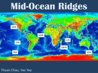
Chapter 13: Mid-Ocean Rifts. The Mid-Ocean Ridge System. Figure 13-1. After Minster et al. (1974) Geophys. J. Roy. Astr. Soc., 36, 541-576. . Oceanic Crust and Upper Mantle Structure. 4 layers distinguished via seismic velocities Deep Sea Drilling Program Dredging of fracture zone scarps

E N D
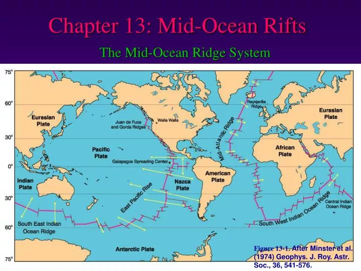
Chapter 13: Mid-Ocean Rifts The Mid-Ocean Ridge System Figure 13-1. After Minster et al. (1974) Geophys. J. Roy. Astr. Soc., 36, 541-576.
Oceanic Crust and Upper Mantle Structure • 4 layers distinguished via seismic velocities • Deep Sea Drilling Program • Dredging of fracture zone scarps • Ophiolites
Oceanic Crust and Upper Mantle Structure Typical Ophiolite Figure 13-3.Lithology and thickness of a typical ophiolite sequence, based on the Samial Ophiolite in Oman. After Boudier and Nicolas (1985) Earth Planet. Sci. Lett., 76, 84-92.
Oceanic Crust and Upper Mantle Structure Layer 1A thin layer of pelagic sediment Figure 13-4. Modified after Brown and Mussett (1993) The Inaccessible Earth: An Integrated View of Its Structure and Composition. Chapman & Hall. London.
Oceanic Crust and Upper Mantle Structure Layer 2 is basaltic Subdivided into two sub-layers Layer 2A & B = pillow basalts Layer 2C = vertical sheeted dikes Figure 13-4. Modified after Brown and Mussett (1993) The Inaccessible Earth: An Integrated View of Its Structure and Composition. Chapman & Hall. London.
Layer 3 more complex and controversialBelieved to be mostly gabbros, crystallized from a shallow axial magma chamber (feeds the dikes and basalts) Layer 3A = upper isotropic and lower, somewhat foliated (“transitional”) gabbros Layer 3B is more layered, & may exhibit cumulate textures
Oceanic Crust and Upper Mantle Structure Discontinuous diorite and tonalite (“plagiogranite”) bodies = late differentiated liquids Figure 13-3.Lithology and thickness of a typical ophiolite sequence, based on the Samial Ophiolite in Oman. After Boudier and Nicolas (1985) Earth Planet. Sci. Lett., 76, 84-92.
Layer 4 = ultramafic rocks Ophiolites: base of 3B grades into layered cumulate wehrlite & gabbro Wehrlite intruded into layered gabbros Below cumulate dunite with harzburgite xenoliths Below this is a tectonite harzburgite and dunite (unmelted residuum of the original mantle)
MgO and FeO • Al2O3 and CaO • SiO2 • Na2O, K2O, TiO2, P2O5 Figure 13-5. “Fenner-type” variation diagrams for basaltic glasses from the Afar region of the MAR. Note different ordinate scales. From Stakes et al. (1984) J. Geophys. Res., 89, 6995-7028.
Ternary Variation Diagrams Example: AFM diagram (alkalis-FeO*-MgO) Figure 8-2. AFM diagram for Crater Lake volcanics, Oregon Cascades. Data compiled by Rick Conrey (personal communication).
Conclusions about MORBs, and the processes beneath mid-ocean ridges • MORBs are not the completely uniform magmas that they were once considered to be • They show chemical trends consistent with fractional crystallization of olivine, plagioclase, and perhaps clinopyroxene • MORBs cannot be primary magmas, but are derivative magmas resulting from fractional crystallization (~ 60%)
Fast ridge segments (EPR) ® a broader range of compositions and a larger proportion of evolved liquids • (magmas erupted slightly off the axis of ridges are more evolved than those at the axis itself) Figure 13-8. Histograms of over 1600 glass compositions from slow and fast mid-ocean ridges. After Sinton and Detrick (1992) J. Geophys. Res., 97, 197-216.
For constant Mg# considerable variation is still apparent. Figure 13-9. Data from Schilling et al. (1983) Amer. J. Sci., 283, 510-586.
Incompatible-rich and incompatible-poor mantle source regions for MORB magmas • N-MORB (normal MORB) taps the depleted upper mantle source • Mg# > 65: K2O < 0.10 TiO2 < 1.0 • E-MORB (enriched MORB, also called P-MORB for plume) taps the (deeper) fertile mantle • Mg# > 65: K2O > 0.10 TiO2 > 1.0
Trace Element and Isotope Chemistry • REE diagram for MORBs Figure 13-10. Data from Schilling et al. (1983) Amer. J. Sci., 283, 510-586.
E-MORBs (squares) enriched over N-MORBs (red triangles): regardless of Mg# • Lack of distinct break suggests three MORB types • E-MORBs La/Sm > 1.8 • N-MORBs La/Sm < 0.7 • T-MORBs (transitional) intermediate values Figure 13-11. Data from Schilling et al. (1983) Amer. J. Sci., 283, 510-586.
N-MORBs: 87Sr/86Sr < 0.7035 and 143Nd/144Nd > 0.5030, ®depleted mantle source • E-MORBs extend to more enriched values ® stronger support distinct mantle reservoirs for N-type and E-type MORBs Figure 13-12. Data from Ito et al. (1987) Chemical Geology, 62, 157-176; and LeRoex et al. (1983) J. Petrol., 24, 267-318.
Conclusions: • MORBs have > 1 source region • The mantle beneath the ocean basins is not homogeneous • N-MORBs tap an upper, depleted mantle • E-MORBs tap a deeper enriched source • T-MORBs = mixing of N- and E- magmas during ascent and/or in shallow chambers
Experimental data: parent was multiply saturated with olivine, cpx, and opx ® P range = 0.8 - 1.2 GPa (25-35 km) Figure 13-10. Data from Schilling et al. (1983) Amer. J. Sci., 283, 510-586.
MORB Petrogenesis Generation • Separation of the plates • Upward motion of mantle material into extended zone • Decompression partial melting associated with near-adiabatic rise • N-MORB melting initiated ~ 60-80 km depth in upper depleted mantle where it inherits depleted trace element and isotopic char. Figure 13-13. After Zindler et al. (1984) Earth Planet. Sci. Lett., 70, 175-195. and Wilson (1989) Igneous Petrogenesis, Kluwer.
Lower enriched mantle reservoir may also be drawn upward and an E-MORBplume initiated Figure 13-13. After Zindler et al. (1984) Earth Planet. Sci. Lett., 70, 175-195. and Wilson (1989) Igneous Petrogenesis, Kluwer.