Download
1 / 38
460 likes | 1.62k Vues
Electromagnetic Blood Flow Meter Dr. Erdem Topsakal, Advisor Brian McCalebb Taffa Porter Kyle Eubanks Nashlie Sephus. Outline. Problem Statement Solution Introduction/Historical Information Technical Constraints Practical Constraints

E N D
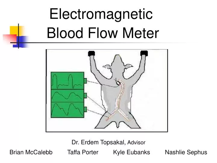
Electromagnetic Blood Flow Meter Dr. Erdem Topsakal, Advisor Brian McCalebb Taffa Porter Kyle Eubanks Nashlie Sephus
Outline • Problem Statement • Solution • Introduction/Historical Information • Technical Constraints • Practical Constraints • Design Approaches/Tradeoffs - Testing Apparatus - Calibration - Probe - Electronics • Timeline • References
Problem • The electromagnetic blood flow meters were originally used by the University of Mississippi Medical Center. • Obtaining replacements is no longer possible. • Other commercially available flow meters proved inadequate.
Solution • Reproduce and improve the original probe • Reproduce similar results to the original meter • Minimum Cost • Dependable • Easy to use • Obtain accurate results
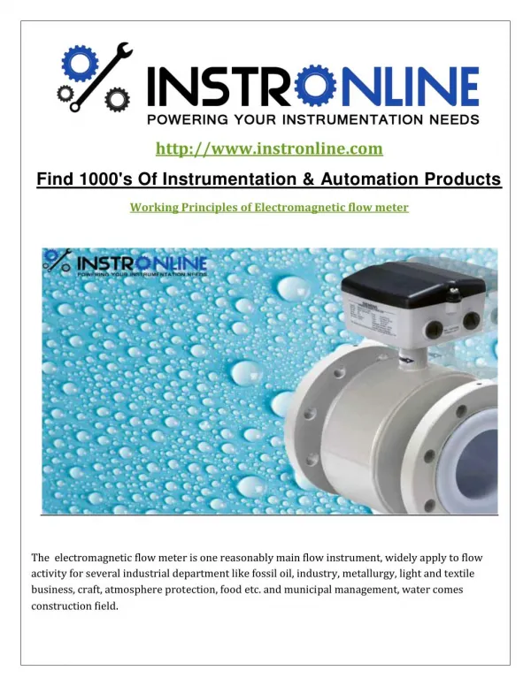
Electromagnetic Blood Flow Meter • What Are Flow Meters? • Electromagnetic blood flow meters measure blood flow in blood vessels • Consists of a probe connected to a flow sensor box
Electromagnetic Blood Flow Meter • Why They Are Used? • Offers quantitative data during surgical operations • Provides a functional assessment of newly joined vessels, grafts and organs • Used in prosthesis in conjunction with cardiovascular surgical procedures • Most accurate results through both acute and chronic implants
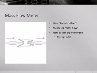
Electromagnetic Blood Flow Meter How Do They Work? • Faraday's Law of Magnetic Induction • Liquid acts as a conductor • Voltage is induced directly related to the average flow velocity • “The faster the flow rate, the higher the voltage” • Voltage is measured by sensing electrodes mounted in the meter tube • Voltage is then sent to the flow sensor box
Outline • Problem Statement • Solution • Introduction/Historical Information • Technical Constraints • Practical Constraints • Design Approaches/Tradeoffs - Testing Apparatus - Calibration - Probe - Electronics • Timeline • References
Measurement Accuracy • Affected by: - Stray magnetic fields detected by electrodes - Non-uniform magnetic field - Turbulent fluid flow - Non-homogenous fluid • Accurate to within ±1 cm/s from 0.1-1 m/s - 10% maximum error at 0.1 m/s - 1% maximum error at 1 m/s
Maximum Fluid Velocity • Fluid velocities in an aorta - 89±9.5 cm/s during heart contraction - 36±6.0 cm/s between contractions • Fluid velocity for flow meter - 1 m/s maximum • Importance of low maximum fluid velocity - Maximizes accuracy for low fluid velocities by allowing more precision in A/D conversion
Conductivity • Calibrated conductivity range • Conductivity of blood - 70 Siemens per centimeter - Varies by up to 20% based on flow rate • Acceptable conductivity range of flow meter - 60–80 Siemens per centimeter
Size • Probe Size • 22 mm inner diameter • Reasoning - Requested by sponsor - Diameter of aorta ranges from 21-35 mm - Larger aortas taper down to smaller diameters
Sustainability • Implanted for 2-3 months • Protection of wire leads, magnetic core, & wire coil • Maintenance of electrodes
Ethical • Designed for cow’s aorta only • Not approved or tested for human use
Outline • Problem Statement • Solution • Introduction/Historical Information • Technical Constraints • Practical Constraints • Design Approaches/Tradeoffs - Testing Apparatus - Calibration - Probe - Electronics • Timeline • References
Testing Apparatus • Via Aqua 1800 - $25.00 - 480 GPH, variable flow rate - 3/4” connections - Saltwater safe • Acrylic tubing - $3.32 / 6ft. - 7/8” OD, 3/4” ID, 1/16” thickness - Insulating material
Testing Apparatus • Dialysis tubing - $5.25 / 10ft - Will be used in future testing - 22 mm diameter - 1 mil thickness - Closely replicates the conductivity of an aorta - May use multiple layers to adjust the conductivity or increase the water pressure it can withstand
Calibration • Calibration and error can be minimized by selecting the proper voltage source waveform • DC - Voltage drift from polarization of electrodes • Sinusoidal AC - Reduces voltage drift by changing polarity - Induces emf in electrodes from magnetic flux variation • Square-wave AC - Reduces voltage drift by changing polarity - Reduces emf in electrodes from magnetic flux variation
Calibration • Why does the output voltage of the probe not directly correlate to the fluid velocity? • Ideally, they are directly proportional • However, sources of error include: - Stray magnetic fields picked up by electrodes - Resistive and capacitive current leakage - Voltage loss through tubing - Voltage drift - Noise
Calibration • Fundamentals of Calibration • Under no flow conditions - Voltage observed is the combination of all sources of error since no voltage from fluid flow • Zero the output waveform - Cancels out all unwanted voltage contributions - Output now has a zero baseline voltage • Output voltage is now directly proportional to the fluid velocity
Calibration • Procedure - The most correct solution is to subtract the entire unwanted waveform - Requires unnecessary computations - Sampling occurs at the same place every cycle - Under no flow, calculate the average voltage at the desired sampling location for every cycle over some period - Subtracting this voltage for every sample gives the voltage contribution due to fluid velocity alone
Outline • Problem Statement • Solution • Introduction/Historical Information • Technical Constraints • Practical Constraints • Design Approaches/Tradeoffs - Testing Apparatus - Calibration - Probe - Electronics • Timeline • References
Probe Key components • Magnetic core • Magnet wire • Electrodes
Probe • Magnetic cores • Permeability - Describes how much a material is affected by magnetic fields and how strong a field it can generate • High permeability results in: - A stronger magnetic field
Probe • Magnetic cores
Probe • Magnet wire Key factors - Thin - Well-insulated - Close to range of 34 gauge (commonly used in industrial electromagnetic blood flow meters) - Availability - Low cost
Probe • Electrodes Desirable qualities • Low resistance - More sensitive • High capacitance - Reduces source impedance and signal attenuation
Electrodes - Capacitance Platinized Platinum Capacitance (µF) Frequency (Hz)
Electrodes - Resistance Resistance (kΩ) Platinized Platinum Frequency (Hz)
Electrodes material Electrodes
Electronics Flow sensor box
References [1] Shercliff, J.A., The Theory of Electromagentic Flow-Measurement. Cambridge: University Press, 1962,pp. 2-4, 125. [2] Flowmeter Directory. Flowmeter Directory. 2007. http://www.flowmeterdirectory.com/flowmeter_electromagnetic.html [3] Tavoularis, S., Measurement in Fluid Mechanics. Cambridge: University Press, 2005, pp. 217. [4] Omega Engineering. Omega Engineering. 2006. http://www.omega.com/techref/flowcontrol.html [5] EesiFlo. Eesiflo. 2007. http://www.eesiflo.com/applications.html [6] Braun, U., and vetJosef, F., “Duplex ultrasonography of the common carotid artery and external jugular vein of cows,” American Journal of Veterinary Research, vol. 66, no. 6, pp.962-965, 2005. [7] Khan, S. R., and Islam, M. N., “Studies on the prospect of bioprostheses by cow aortic valve for human use,” Bangladesh Med Res Counc Bull, vol. 17, no. 2, pp. 75-80, 1991. [8] Wyatt, D. G., and Phil, D., "Problems in the Measurement of Blood Flow by Magnetic Induction," Phys. Med. Biol., vol. 5, pp. 369-399, 1961.