Download

1 / 44
710 likes | 1.19k Vues
Single Phase Motors. Topic 3: Testing Single Phase Motors. Assumed prior learning. 05_01_00 05_01_02 05_02_01. Outcomes. By the end of this unit the learner will: List the necessary single phase motor electrical tests Perform continuity tests on single phase motors

E N D
Single Phase Motors Topic 3: Testing Single Phase Motors
Assumed prior learning 05_01_00 05_01_02 05_02_01
Outcomes By the end of this unit the learner will: • List the necessary single phase motor electrical tests • Perform continuity tests on single phase motors • Perform capacitor tests on single phase motors • Perform insulation resistance tests on single phase motors • Complete a motor test form with the results of electrical tests
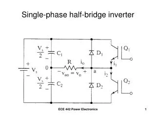
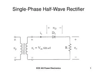
Introduction Nothing in life is perfect and single phase AC motors are the same. They need to be regularly checked, tested and repaired to keep them in running order. Sometimes things break and then we need to test motors to find out why. Some motor faults can even lead to death like when there is a short circuit between the windings and the motor frame. In this unit, we are going to learn about how to do all the necessary electrical tests on a single phase motor.
Introduction [Img1]You work for a large food retailer and receive a call that one of the roller doors at the main warehouse is not working. Your job is to test the single phase motor controlling the door and see if you can figure out what is wrong with it.
Safety first When you work with motors you must put your safety and the safety of others first. You must complete the necessary Hazard Identification and Control (HIAC) Form. Need help with HIACs? Click the button to go to Topic X in The World of an Electrician Get help with HIAC Forms
Potential Hazards Here are some of the potential hazards you should look out for: Vehicles, traffic or mobile equipment Working at heights above 2m Lifting and material handling Hazardous Materials or Waste Electricity, machinery, stored energy or machine isolation Work with Oxy-fuel gas mixtures
What are the Potential Hazards? Img02 You need to test a single phase AC motor. • It operates a 2.5m high roller door for a delivery truck entrance. • The motor is mounted on a bracket next to the roller mechanism. Identify all the hazards that are present. Identify the hazards
Potential Hazards Which hazards apply to this situation? Drag them onto the picture. Img02 Vehicles, traffic or mobile equipment Hazardous Materials or Waste Working at heights above 2m Lifting and material handling Electricity, machinery, stored energy or machine isolation Work with Oxy-fuel gas mixtures Check
Stop and Check? Because there are some potential hazards associated with this job, you need to check that all the necessary safety controls related to these hazards are in place. If you are not sure what these safety controls are, you should stop this unit and refer back to Topic X in The World of an Electrician before continuing. Learn about Safety Controls
Before We Begin Before you do any electrical tests, you must make sure that you have isolated and locked out the supply to the motor. Make sure you know how to do this by referring to Topic X in The World of An Electrician. Learn about Isolating and Lock-Out Procedures
Be Prepared Check you multimeter 1 Once you have • Identified all potential hazards • Made sure the necessary safety controls are in place • Isolated and locked out the motor, you can prepare to start your tests. Open the terminal box 2 Remove the bridge pieces 3 Click on each box to learn more.
Open the Terminal Box You do not need to open up the motor to test it. You can access all the motor’s electrical components and terminals from inside the terminal box. Img05 Img06 Look out for a wiring diagram on the inside of the terminal box cover showing how everything is connected to the terminal block
Remove the Bridge Pieces Img08 You might see some of the terminals connected or bridged with strips of metal. These allow you to control the direction of the motor. If you see bridge pieces, disconnect them. Img09
A Note on Wiring Diagrams The names that different manufacturers give to each terminal may differ but U1, V1, W1, U2, V2 and W2 are quite common. The wiring diagram gives details about how to wire the motor including where to place the bridge pieces in order to control its direction. Take note of the wire colours that are given.
Types of Electrical Tests There are basically three types of electrical tests that you need to be able to do on single phase AC motors. Click on each box to find out more. Continuity Tests Capacitor Tests Insulation Resistance Tests
Continuity Tests Now you are ready to start with the continuity tests. Click each step to see what to do. Step 3 Step 1 Step 2 Step 4
Step 1 Img10 Set your multimeter to the continuity setting which is often the same as the low Ω setting.
Step 2 Img11 • Draw the terminal block connections on a piece of paper if you do not have a printed diagram. • If there is a wiring diagram available label the terminals in your diagram like the wiring diagram. • Make sure that you have an electrical checklist to note down all your test results. Img12
Step 3 Img13 • Clip the black lead onto the top left terminal and test each of the other terminals to see which one shows continuity. • Your multimeter will show a resistance value and might beep. • Mark these two terminals and note the total resistance. Img14
Step 4 Img15 • Connect the black lead to the next terminal and repeat the process until you have connected the black lead to all of the terminals. • Mark which terminals are connected and what the resistance value is in each case.
Doing a Continuity Test Watch a video to see how to do a continuity test and to learn what the readings mean. Vid01
Complete a Motor Test Form Here is part of a typical motor test form. Img16 • Click on the image to download the form or make your own. • Look at the test values. • Indicate the following: • Start windings • Run windings • Centrifugal switch See the test values
Test Values V1 – W1: None U1 – V1: 7,3Ω U1 – W1: None U2 – V3: None U2 – U1: None U2 – V1: None U2 – W1: 21,4Ω V2 – U1: None V2 – V1: None V2 – W1: None W2 – U2: None W2 – V2: 0,4Ω W2 – U1: None W2 – V1: None W2 – W1: None
Upload Your Motor Test Form Take a picture of your completed form and upload it. Make sure you have labelled the block diagram with which connections represent the start winding, the run winding and the centrifugal switch and what these resistance values are. Choose image Upload
Your Motor Test Form Img18 Your completed form should have looked something like this. • The centrifugal switch has a resistance close to zero. • The start winding always has a resistance greater than the run winding.
What’s the Problem? The run winding is damaged The start winding is damaged The centrifugal switch is damaged There is nothing wrong Look at the test results and decide what is wrong with this motor. See the test results
Test Values T5 – T6: None T4 – T5: 7,3Ω T4 – T6: None T2 – T3: None T2 – T4: None T2 – T5: None T2 – T6: 21,4Ω T3 – T4: None T3 – T5: None T3 – T6: None T1 – T2: None T1 – T3: 0,4Ω T1 – T3: None T1 – T5: None T1 – T6: None
Complete the Motor Test Form Img19a Here is a full motor test form. Download this form or create your own. Complete the relevant section with the test results provided on the previous screen. See the test results again Download
Capacitor Test Vid02 We need to test the motor’s capacitor to see if an open or short circuit condition exists. Generally, if a capacitor is found to be faulty, it must be replaced. Watch the video to learn how to test a capacitor
Remember - Use the Right Instrument! Img21 It is best to do a capacitor test with a good quality analogue multimeter. You must NEVER use an insulation resistance tester like the BM6 Megger to test a capacitor. When the capacitor discharges, it will destroy the instrument.
Complete the Motor Test Form Img19a Continue to complete your full motor test form with the results of these capacitor tests. See the test results Download
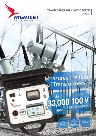
Insulation Resistance Tests Img22 Electricity is very useful but only when it flows where we want it to! 1 Insulation resistance tests check if there is any breakdown in the insulation between a motor’s electrical components. 2 It is best to use an insulation resistance tester for these tests because of the high test voltages they produce.
Insulation Resistance Tests We need to do four tests: Test the insulation between the windings. 1 Test the insulation between the windings and the capacitor. Watch how to do these insulation resistance tests 2 Test the insulation between the windings and the centrifugal switch. 3 Test the insulation between the components and the motor frame. 4
Complete the Motor Test Form Img19a Continue to complete your full motor test form with the results of these insulation resistance tests. See the test results Download
Upload Your Full Motor Test Form Now take a picture of your completed form and upload it. Make sure that all the columns have been completed as well as your final assessment as to whether this motor is electrically acceptable or not. Choose image Upload
Get Some Practice Img21 Are you ready to do a full electrical test on a single phase motor? Try this single phase motor test simulator. Launch the simulator
Video Briefing – Vid01 Video of an electrician demonstrating how to do a continuity test. Pay special attention to • Setting the multimeter to the correct setting • Interpreting a wiring diagram including reversing directions and when to connect the supply • The process and sequence of connecting the leads • Seeing when the meter gives a reading and what this is • Run – if continuous will give a resistance value • Start – if continuous will give a resistance value • Switch – if properly closed will give a resistance reading near to zero. Burnt contacts or carbon build up can make value as high as 0,5 ohms • Connecting the terminals on the diagram and noting the resistance values • Analysing the resistance values and identifying the components by these values • Start winding larger than run winding • Centrifugal switch close to zero • Repeat the test on a damaged motor and show readings obtained for • Damaged start winding and how to tell if the start or run winding is faulty • Damaged switch • Demonstrate how to complete a motor test form with these results
Video Briefing – Vid02 Video of an electrician demonstrating how to test a capacitor. Pay special attention to • Using a multimeter – preferably analogue • selecting high ohms setting • Shorting leads and adjusting meter to read 0 ohms • Not using an insulation resistance tester and WHY • When the meg-ohm scale is selected on the megger, the testing voltage is 500 volt. If the capacitor is now tested on this range, it will be charged with the 500 volt. At the instant that the test button is released, that voltage will discharged back through the instrument, damaging it. • Identifying and isolating the terminals of the capacitor for both start and run if necessary • Resistance readings for working capacitor – swing quickly to 0 and then gradually rise to infinity as the capacitor charges • Connect capacitor in both directions • Charge time shorter and deflection smaller for smaller run capacitors • Recording results on checklist with comments • Demonstrate what short and open circuited results looks like and what to do. • Demonstrate how to complete a motor test form with these results.
Video Briefing – Vid03 Show results of 2 capacitor tests • Start capacitor – needle deflects to zero and then rises to infinity • Run capacitor – needles remains at infinity
Video Briefing – Vid04 Video of an electrician demonstrating how to test a do insulation resistance tests. Pay special attention to: • Required insulation resistance tester setting selection • Procedure to test insulation between windings and allowed readings • Procedure to test insulation between windings and capacitors and switch and allowed readings • Procedure to test insulation between run, start, switch and capacitor(s) and earth and allowed readings • How to complete the motor test form • Make sure to include at least 1 test that fails
Video Briefing – Vid05 Show results of insulation resistance tests • RW – SW: Infinity • RW – CS: Infinity • SW – CS: Infinity • RW – CAP: 2kΩ • SW – CAP: Infinity • CAP – CS: 3.5kΩ • RW – E: Infinity • SW – E: Infinity • CAP – E: 6.2kΩ • CS – E: Infinity