Download
1 / 12
120 likes | 279 Vues
MAE 435 Chris Cook Jeffry Walker Joshua Beverly Miguel de Rojas. 5-DOF Anthropomorphic Manipulator. Project Scope & Outline. Design, Fabricate and Control 5DOF ARM. Conceptual Design. Analysis. Final Design. Machine Parts. Assembly. Kinematics. Inverse Kinematics. Dynamics.

E N D
MAE 435 Chris Cook Jeffry Walker Joshua Beverly Miguel de Rojas 5-DOF Anthropomorphic Manipulator
Project Scope & Outline • Design, Fabricate and Control 5DOF ARM Conceptual Design Analysis Final Design Machine Parts Assembly Kinematics Inverse Kinematics Dynamics Develop Controls Physical Testing • GOAL: Place 5cm x 5cm x 5cm cube within 6in radial • distance of desired position with some degree of repeatability.
Preliminary Calculations • Used to determine motor and gearbox sizing JointMass=.939; %mass of joint (kg) ShaftMass=.113; %mass of shaft (kg) ShaftLength=.2032; %length of shaft (m) MotorOutput=.4862; %N-m output torque peak effective GearRation=132; %ratio of planetary gearbox LoadLifted=.34; %minimum mass to be picked up (kg) g=9.81; %gravity %effective forces jf=JointMass*g; sf=ShaftMass*g; lf=LoadLifted*g; L=ShaftLength; %Joint Torques J1torque=lf*3*L+jf*L*(3+2+1)+sf*L*(2.5+1.5+.5); J2torque=lf*2*L+jf*L*(2+1)+sf*L*(1.5+.5); J3torque=lf*L+jf*L+sf*L*.5;
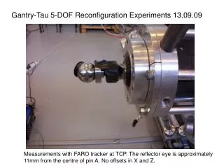
Machining & Assembly • Components Machined Primarily • with a Lathe and 3 Axis Mill using • 6061 Aluminum
Solid Model • Accurately Represents Physical Structure • Used to Export Physical Data for Kinematics and Control Design
Wiring and Final Assembly • Wiring harness created using soldered pin connectors. • Custom printed circuit board from ExpressPCB used to connect multiple encoder boards • Stack used for motor controller organization.
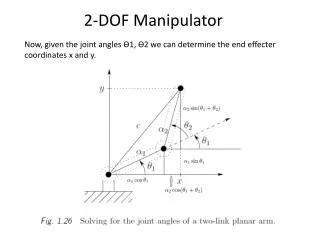
Forward Kinematics • Precursor to Inverse Kinematics and Dynamics • Limitations in time prohibited development of Dynamics
Control Design • Experimental System Identification Utilized to Initially Estimate PID Gains • Position data collected by arbitrary input signal thereby capturing system response • Biggest Obstacle was Overcoming Adverse Effects of Gravity • Feed-Forward Gravity term used to compensate • Adaptive Logic used in addition to PID to overcome limitations and undesirable system characteristics • System Integration by unifying control logic regulating position signals to individual joint controllers Simplified Eqn. governing gravity FF. This function is dependent upon the joint angle which changes the effective moment arm.
Gravity Feed-Forward Implementation Diagram of the second joint gravity feed-forward. The position of the second and third joint is used to calculate the effective moment arm for the respective masses. Further logic used to refine control signals, however too complex to be adequately presented.
Outcomes • ARM can be preset to positions resulting in a 5deg/joint accuracy • This accuracy is highly dependent on chosen joint position and is subject to random abnormalities • Insufficient time and unexpected technical difficulties prohibited sufficient refinement to control system required for satisfactory object interaction tasks • Following clip displays attempt at object interaction. • Manual interaction was required as unexpected miscommunication in electronics induced unsatisfactory system response- this issue has since been resolved. • Unexplained loss of power to second joint at end of clip resulted in arm falling. Object Interacting Attempt