Download
1 / 26
340 likes | 752 Vues
A F M. Atomic Force Microscope. Joshua Norem Joel Jordan ECE 345 University of Illinois. Original Project Goals. A F M. Develop coarse positioning to move a sample into scanning position Design optical feedback system to control positioning and provide surface height information

E N D
A F M Atomic Force Microscope Joshua Norem Joel Jordan ECE 345 University of Illinois
Original Project Goals A F M • Develop coarse positioning to move a sample into scanning position • Design optical feedback system to control positioning and provide surface height information • Enable fine positioning of sample in two directions • Write PC software to control entire system via serial link to Digital Signal Processor board
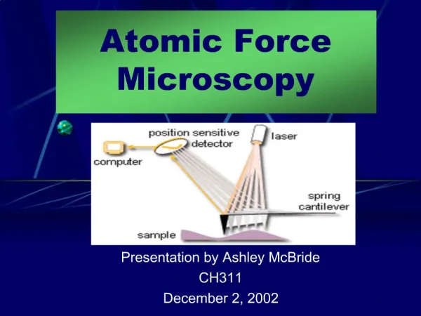
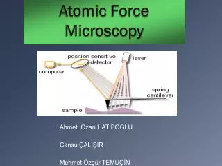
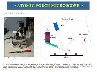
Principle of Operation A F M
Coarse Positioning System A F M • Apply a voltage to piezoelectric tube to move a platform • Place movable sled on platform to hold fine positioning system with sample • Move sled slowly forward, then snap backwards fast enough to overcome static friction so that the sled will not move • Repeat process until the sled has moved close enough to the scanning tip to deflect it
Fine Positioning System A F M • Second piezoelectric tube has voltages applied separately to four quadrants • Sub-micrometer positioning can be achieved in X-, Y-, and Z- axes • Sample is moved so that tip barely contacts surface constantly, Z position of sample corresponds to height of sample at that point
Optical Feedback System A F M • Laser focused on AFM cantilever tip, reflects off and hits segmented photodiode • Segmented photodiode has two adjacent sensors • Position of laser can be determined by subtracting two photodiode outputs • Ambient light cancelled out by subtraction • Tiny movements in cantilever tip cause much larger movements of reflected laser
Accomplishments A F M • Designed and built stage on which to mount all components • Built optical feedback circuit • Developed code required for coarse positioning system on TMS320C54x Digital Signal Processor platform • Developed code required for serial interface with host PC to control AFM operation
AFM Stage Design A F M
Stage Details A F M • Rests on top of concrete patio block hung from ceiling for vibration isolation. • Also includes separate free floating sled
Actual Stage Design (side) A F M .24” 1.1” 2.2” .125” .24” .24” .125” 1.3” 1.5”
Actual Stage Design (top) A F M 3” .5” 1.5” 2.9” 9” .25” 1” 6.75” 1.1”
Sled A F M Side Top Front 1.6” 1.25” 1.6” 19” .5” 1” 1.5” 1.25”
Optical Feedback System A F M
Optical Feedback System A F M • Board laid out on computer, printed onto paper cut out of a magazine • Design transferred to plain copper board with a normal iron • Board etched in ferric chloride • Circuit uses ultra-low noise Burr-Brown instrumentation op-amps as transimpedance amplifiers
Optical Feedback System A F M
Optical Feedback System A F M • Measurement taken from both sensors in photodiode while laser is pointed directly at the middle. • Visible variations caused by shaking from the hand holding the laser. • Noise is present on scope even in absence of any signal
Optical Feedback System A F M • When laser is moved off-center of photodetector, maximum separation of input signals is about 500mV
Optical Feedback System A F M • As laser is swept from one side of the detector to the other, difference is clearly visible
Coarse Positioning System A F M • DSP generates sawtooth wave to move platform either forward or backward • When laser moves from the center of the photodetector, the DSP stops the platform movement • All tasks function zed for easy code maintenance.
Waveform A F M • Problems with audio dac/dsp core • Result: aprox. 1.2ms cycle time • Basic saw tooth • involves Speed Vs. clarity tradeoff
Serial Interface A F M • Allows control of coarse positioning system over serial port • Reports status of optical feedback system, used to calibrate and determine height of sample in fine positioning mode
Problems A F M • Getting parts took much longer than expected due to communications problems • Some critical operational amplifiers were never delivered for some reason • Without critical operational amplifiers, piezoelectric tubes could not even be tested, since lab equipment could not generate test waveforms at high enough voltages • Code Composer software for DSP took extra time to be installed and setup
Lessons Learned A F M • Getting specialized parts requires constant monitoring at all points in the process • Assume nothing about software installed on lab machines – always check to see that what you need is there
Still Left To Do A F M • Fine positioning system needs to be implemented • High-voltage operational amplifiers need to be received • Some type of holder for the AFM tip needs to be designed and built • Optical elements for focusing the laser need to be incorporated into design
Is it worth it? A F M • Unit production cost and order of magnitude lower than current AFM’s • Modularity for easy component upgrade • Broad application in small educational situations such as high schools • Strong hobbyist appeal YES!!!
Questions? A F M