Download
1 / 14
140 likes | 224 Vues
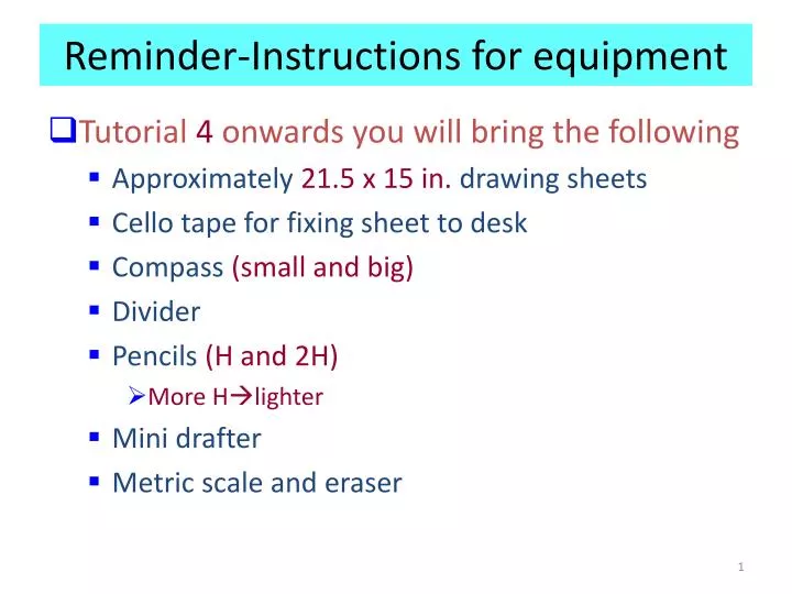
Reminder-Instructions for equipment. Tutorial 4 onwards you will bring the following Approximately 21.5 x 15 in. drawing sheets Cello tape for fixing sheet to desk Compass (small and big) Divider Pencils (H and 2H) More H lighter Mini drafter Metric scale and eraser.

E N D
Reminder-Instructions for equipment • Tutorial 4 onwards you will bring the following • Approximately 21.5 x 15 in. drawing sheets • Cello tape for fixing sheet to desk • Compass (small and big) • Divider • Pencils (H and 2H) • More Hlighter • Mini drafter • Metric scale and eraser
Mini Drafter (Tutorial 4 onwards) A mini drafter is a portable device used to draw parallel, inclined and perpendicular lines speedily. It is mounted on a drawing board at the top left corner. A drafter consists of a scale, a scale screw, a scale plate, steel bars, a bar plate and a clamping mechanism
Oblique projection Plane of projection e, h a, e a, d d, h h e d a b, c f, g c, g b, f f g c b Face abcd retains original shape and dimensions Projection lines are oblique to the plane
Drawing an oblique projection Axes are drawn such that two of them are perpendicular to each other for the front face (horizontal and vertical) and the third is drawn at a pre-defined angle (use 45o in this course) to horizontal axis Lines drawn in true length y This face will have features with true shape z Receding line a Receding angle x o ataken as 45o Oblique view of a cuboid Draw essential contours (circles, curves etc.) on this face
Oblique view • It is a method of drawing a 3-D view of an object (similar to isometric view) • 2 axes are mutually perpendicular while the 3rd. axis is at an angle (other than 90o to the other 2 axes)
Object Orientation Guidelines Place complex features (arc, hole, irregular shape surface parallel to frontal plane.
Cavalier and cabinet projection • Two types of oblique projection • Cavalier projection: When the receding lines are drawn to full size scale and the projectors are inclined at an angle of 30o, 45o, or 60o • Cabinet projection: If the receding lines are drawn to half size scale. We use Cavalier Projection in this course
PROJECTIONS OF PLANES • A plane is a two-dimensional geometrical entity • It has length and width but no thickness • For practical purposes, a flat face of an object may be treated as a plane • A plane which has limited extent (has fixed shape) is termed as a lamina • Information usually given: • Shape of the plane • Inclination of it’s surface with one of the reference (principal) planes • Inclination of one of it’sedgeswith the otherreference plane will be given
For Tv For T.V. For T.V. For Fv For F.V. For F.V. VP VP VP c1’ d1’ c’ b’ b’ c’ a1’ d’ a’ B A C b1’ d’ a’ d1 d1 a1 a d a1 b c b1 b1 c1 c1 HP HP HP ONE SMALL SIDE INCLINED TO VP PICTORIAL PRESENTATION SURFACE INCLINEDTO HP PICTORIAL PRESENTATION SURFACE PARALLELTO HP PICTORIAL PRESENTATION FV-1 FV-2 FV-3 T V-1 T V-2 T V-3 ORTHOGRAPHIC FV- Apparent Shape TV-Previous Shape ORTHOGRAPHIC TV-True Shape FV- Line // to xy ORTHOGRAPHIC FV- Inclined to XY TV- Reduced Shape
Rectangle 30mm and 50mm sides is resting on HP on one small side which is 300 inclined to VP, while the surface of the plane makes 450 inclination with HP. Draw it’s projections. Surface // to Hp Surface inclined to Hp c’1 d’1 c’ d’ c’ d’ b’ a’ a’ b’ b’1 a’1 450 Y X 300 a a1 a1 d1 d Side Inclined to Vp b1 c d1 b b1 c1 c1
Drawing the side view w w T O w F 45o T F O w RSV RSV With O as center draw curves (1/4 circle) to project the corners Draw a line from O at 45o to the horizontal axis to project the corners
SOLIDS Dimensional parameters of different solids. Cone Cylinder Square Prism Square Pyramid Apex Apex Top Slant Edge Rectangular Face Triangular Face Base Base Base Longer Edge Base Edge of Base Corner of base Edge of Base Corner of base Generators Imaginary lines generating curved surface of cylinder & cone. Frustum of cone & pyramids. ( top & base parallel to each other) Sections of solids( top & base not parallel)
Solution Steps: Resting on Hp on one generator, means lying on Hp: 1.Assume it standing on Hp. 2.It’s Tv will show True Shape of base( circle ) 3.Draw 40mm dia. Circle as Tv & taking 50 mm axis project Fv. ( a triangle) 4.Name all points as shown in illustration. 5.Draw 2nd Fv in lying position I.e.o’e’ on xy. And project it’s Tv below xy. 6.Make visible lines dark and hidden dotted, as per the procedure. 7.Then construct remaining inclination with Vp ( generator o1e1 300 to xy as shown) & project final Fv. a’1 h’1 b’1 g’1 e’ a’ c’g’ d’f’ h’b’ f’1 c’1 o’ d’1 e’1 g1 g1 h1 f1 h1 f1 a1 e1 a1 b1 e1 b1 d1 d1 c1 c1 Problem: A cone 40 mm diameter and 50 mm height is resting on one generator on Hp which makes 300 inclination with Vp Draw it’s projections. Draw in 1st.angle o’ Y o1 X a’ h’ b’ c’ g’ f’ e’ d’ 30 g o1 h f a o1 e b d c