Download
1 / 63
680 likes | 1.43k Vues
L5 Refractive index and Polarization. Chii-Wann Lin. Contents. Fundamental optics Refractive index Polarization Optical dispersion in materials Relative Permittivity and Refractive Index. Wavelengths of “Light”. nm : for near UV, visible, and near IR light m m : for IR and far IR light

E N D
L5 Refractive index and Polarization Chii-Wann Lin
Contents • Fundamental optics • Refractive index • Polarization • Optical dispersion in materialsRelative Permittivity and Refractive Index
Wavelengths of “Light” nm: for near UV, visible, and near IR light mm: for IR and far IR light Å: for x-ray. But in this regime people usually use photon energy in eV.
Light Wave • Plane electromagnetic wave (traveling wave) • k: propagation constant or wave number • w: angular frequency • Phase of the wave (wt –kz+f0) • Wave front : A surface over which the phase of a wave is constant. • Optical field : refers to the electrical field Ex. Traveling wave along Z
Point or Plane source Gaussian beam with waist radius w and spot size 2w Divergence No divergence Divergence
Wavefront Wavefront: surfaces of constant phase for the electromagnetic field . l
Propagation of Light Light is a kind of electro-magnetic wave. A: amplitude vector. f: phase.
Wave Vector and Wave number Wave Vector, k: Use to indicate the direction of propagation. The vector whose direction is normal to the wavefront, and magnitude is k = 2p/l. For a plane wave, A is constant, and k The magnitude of k, k = 2p/l, is also called the wave number.
Phase velocity • The relationship between time and space for a given phase, f, that corresponding to a maximum field, can be described by • So, during a time interval dt, this const phase (max. field) moves a distance dz. Thus defines the phase velocity of this wave as
Meaning what? • We are frequently interested in the phase difference Df, at a given time between two points on a wave that are separated by a certain distance. • If the wave is traveling along z with a wavevector k, then the phase difference between two points separated by Dz is simply kDz since wt is the same for each point. • If this phase difference is 0 or multiples of 2p then the two points are in phase. Phase difference Df can be expressed as kDz or 2pDz/l.
Phase Velocity and Group Velocity Phase velocity If we have two frequency components, w + Dw and w - Dw , the envelope moves with a speed is called group velocity. In the limit, The group velocity defines the speed with which energy or information is propagated since it defines the speed of the envelope of the amplitude variation. In vacuum, the group velocity is equal to phase velocity. Suppose that v depends on the wavelength or k by virtue of n being a function of the wavelength as in the case for glass. Then,
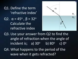
Refractive Index • When an EM wave is traveling in a dielectric medium, the oscillating electric field polarizes the molecules of the medium at the frequency of the wave. • The field and the induced molecular dipoles become coupled. The net effect is that the polarization mechanism delays the propagation of the EM wave. • In other words, it slows down the EM wave with respect to its speed in a vacuum. The stronger the interaction between the field and the dipole, the slower the propagation of the wave. • The ratio of the speed of light in free space to its speed in a medium is called the refractive index n of the medium. • Definition of refractive index: V : phase velocity in a nonmagnetic dielectric medium er : relative permittivity
Relative permittivity • The relative permittivity measures the ease with which the medium becomes polarized and hence it indicates the extent of interaction between the field and the induced dipoles. • For an EM wave traveling in a nonmagnetic dielectric medium of relative permittivity er, the phase velocity v is given by: • For an EM wave traveling in free space of vacuum, er=1 and vvacuum = c = 3x10⁸ ms-1. • If k is the wave vector (k = 2p/l) and l is the wavelength in free space, then in the medium kmedium = nk and lmedium =l/n.
The refractive index of materials in general depends on the frequency, or the wavelength, of light. This wavelength dependence follows directly from the frequency dependence of the relative permittivity εr.(相對介電係數 ) • In the absence of an electric field and in equilibrium, the center of mass C of the orbital motions of the electrons coincides with the positively charged nucleus at O and the net electric dipole moment is zero as indicated in Figure 1 (a). • Suppose that the atom has Z number of electrons orbiting the nucleus and all the electrons are contained within a given shell. In the presence of the electric field E, however, the light electrons become displaced in the opposite direction to the field so that their center of mass C is shifted by some distance x with respect to the nucleus O which we take to be the origin as shown in Figure 1 (b).
As the electrons are "pushed" away by the applied field, the Coulombic attraction between the electrons and nuclear charge "pulls in" the electrons. The force on the electrons, due to E, trying to separate them away from the nuclear charge is ZeE. • The restoring force Fr which is the Coulombic attractive force between the electrons and the nucleus, can be taken to be proportional to the displacement x provided that the latter is small. The reason is that Fr = Fr(x) can be expanded in powers of x and for small x only the linear term matters. The restoring force Fr is obviously zero when C coincides with O (x = 0). We can write Fr = − βx where β is a constant and the negative sign indicates that Fr is always directed towards the nucleus O. • First consider applying a dc field. In equilibrium, the net force on the negative charge is zero or ZeE = βx from which x is known. Therefore the magnitude of the induced electronic dipole moment is given by pinduced = (Ze)x = (Z2e2/ β)E Induced electronic dc dipole moment (1)
As expected pinduced is proportional to the applied field. The electronic dipole moment in Eq. (1) is valid under static conditions, i.e. when the electric field is a dc field. Suppose that we suddenly remove the applied electric field polarizing the atom. There is then only the restoring force, – β x, which always acts to pull the electrons towards the nucleus, O. The equation of motion of the negative charge center is then (force = mass × acceleration) – β x = Zmed2x/dt2 • Thus, by solving this differential equation, the displacement at any time is a simple harmonic motion, that is x(t) = xocos( ωot) where the angular frequency of oscillation ωois
In essence, this is the oscillation frequency of the center of mass of the electron cloud about the nucleus and xo is the displacement before the removal of the field. After the removal of the field, the electronic charge cloud executes simple harmonic motion about the nucleus with a natural frequency ωodetermined by Eq. (2); ωois also called the resonance frequency. • The oscillations of course die out with time because there is an inevitable loss of energy from an oscillating charge cloud. An oscillating electron is like an oscillating current and loses energy by radiating electromagnetic waves; all accelerating charges emit radiation.
Consider now the presence of an oscillating electric field due to an electromagnetic wave passing through the location of this atom as in Figure 1 (b). The applied field oscillates harmonically in the +x and −x directions, that is E = Eoexp(j ωt). This field will drive and oscillate the electrons about the nucleus. There is again a restoring force Fr acting on the displaced electrons trying to bring back the electron shell to its equilibrium placement around the nucleus. For simplicity we will again neglect energy losses. Newton’s second law for Ze electrons with mass Zmedriven by E is given by, The solution of this equation gives the instantaneous displacement x(t) of the center of mass of electrons from the nucleus (C from O),
The induced electronic dipole moment is then simply given by pinduced = −(Ze)x. The negative sign is needed because normally x is measured from negative to positive charge whereas in Figure 1 it is measured from the central nucleus. • By definition, the electronic polarizability αeis the induced dipole moment per unit electric field, Thus, the displacement x and hence electronic polarizability αeincrease as ωincreases. Both become very large when ω approaches the natural frequency ωo. In practice,charge separation x and hence polarizability αedo not become infinite at ω = ωobecause two factors impose a limit. First is that at large x, the system is no longer linear and the above analysis is not valid. Secondly, there is always some energy loss.
Given that the polarizability is frequency dependent as in Eq. (3), the effect on the refractive index nis easy to predict. The simplest (and a very “rough”) relationship between the relative permittivity εr and polarizability αeis • where N is the number of atoms per unit volume. Given that the refractive index n is related to εrby n2 = εr, it is clear that n must be frequency dependent, i.e.
We can also express this in terms of the wavelength λ. If λo = 2 πc/ ωo is the resonance wavelength, then Eq. (4) is equivalent to This type of relationship between n and the frequency ω, or wavelength λ, is called a dispersion relation. The refractive index n decreases as the wavelength λ increases above and away from the resonance wavelength λoas illustrated schematically in Figure 2.
Dispersion and Light Extinction • Consider an atom in a material as in Figure 1 that is experiencing an alternating field E that oscillates harmonically in the +x and −x directions, that is E = Eoexp(j ωt). The electrons are driven by this field. There is a restoring force Fr acting on the displaced electrons trying to bring back the electron shell to its equilibrium placement around the nucleus. This force Fr is proportional to the displacement x and is always directed towards the center O; it can be written as − βx. • Oscillating electrons are equivalent to an oscillating current which radiates energy like an antenna. This is an effective loss of energy, just like a frictional force. Further, some of the electron oscillations can be coupled to crystal vibrations and increase their energy, that is, energy will be transferred from electron oscillations to heat. All energy losses are proportional to the velocity dx/dt and the equivalent frictional force per electron and per unit electron mass is γdx/dt. Thus, Newton’s second law for Ze electrons with mass Zme is given by, where Zme ωo2 is the force constant β.
Solving this equation we obtain the instantaneous displacement x = x(t) of the center of mass C of the electron shell from the nucleus O in Figure 1. Once we know x(t) we can easily find the electronic polarizability αe, where ωo =( β/Zme)1/2. It is a resonance frequency where αe peaks. We can easily separate this complex αe into real and imaginary parts as
The frequency dependences of the real and imaginary parts of αe are shown in Figure 3. It is important to recognize that αe″ is directly proportional to the loss coefficient γ which means that the imaginary part αe″ represents the loss in the medium. The real part is not significantly affected by γ if ω is sufficiently smaller than ωo. At resonance (at ω = ωo) however, αe′ does not peak to infinity; its maximum is controlled by the loss mechanism. • Since αe is a complex quantity, so is εrand hence the refractive index. Consider the simplest (and very “rough”) relationship between the relative permittivity εrand polarizability αe, where N is the number of atoms per unit volume.
Thus, the relative permittivity is a complex quantity, that is The real part is the usual relationship between the relative permittivity and polarizability when loss is neglected. Clearly the imaginary part represents the loss, the extinction of light as it passes through the material. There are always some losses in all polarization processes. For example, when the ions of an ionic crystal are displaced from their equilibrium positions by an alternating electric field and made to oscillate, some of the energy from the electric field is coupled and converted to lattice vibrations (intuitively, “sound” and heat). These losses are generally accounted by describing the whole medium in terms of a complex relative permittivity (or dielectric constant) εras in Eq. (7) where the real part εr′ determines the polarization of the medium with losses ignored and the imaginary part εr ′′ describes the losses in the medium.
For a lossless medium, obviously εr = εr′.The loss εr ′′ depends on the frequency of the wave and usually peaks at certain natural (resonant) frequencies. If the medium has a finite conductivity (e.g. due to a small number of conduction electrons), then there will be a Joule loss due to the electric field in the wave driving these conduction electrons. This type of light attenuation is called free carrier absorption. In such cases, εr ′′ and σ are related by where εois the absolute permittivity and σ is the conductivity at the frequency of the EM wave. Since εris a complex quantity, we should also expect to have a complex refractive index. An EM wave that is traveling in a medium and experiencing attenuation due to absorption can be generally described by a complex propagation constant k, that is k = k′ − jk″ Complex propagation constant (10) where k′ and k″ are the real and imaginary parts. If we put Eq. (10) into the expression for an ideal traveling wave, E = Eoexpj( ωt − kz) we will find the following E = Eoexp(−k″z)expj( ωt − k′z) Attenuated propagation (11)
The real k′ part of the complex propagation constant (wavevector) describes the propagation characteristics, e.g. phase velocity v = ω/k′. The imaginary k″ part describes the rate of attenuation along z. The intensity I at any point along z is I ∝|E|2 ∝ exp(−2k″z) so that the rate of change in the intensity is dI/dz = −2k″I Imaginary part k ″ (12) where the negative sign represents attenuation. • Suppose that ko is the propagation constant in vacuum. This is a real quantity as a plane wave suffers no loss in free space. The complex refractive index Ν with real part n and imaginary part Kis defined as the ratio of the complex propagation constant in a medium to propagation constant in free space, Ν = n − jK = k/ko = (1/ko)[k′ − jk″] Complex refractive index (13) i.e. n = k′/ko and K = k″/ko
The real part n is simply and generally called the refractive index and K is called the extinction coefficient. In the absence of attenuation, k″ = 0, k = k′ and Ν = n = k/ko = k′/ko. • We know that in the absence of loss, the relationship between the refractive index n and the relative permittivity εris n = √ εr. This relationship is also valid in the presence of loss except that we must use complex refractive index and complex relative permittivity, that is, Ν = n − jK= √ εr = √( εr ′ − j εr″) Complex refractive index (14) • By squaring both sides we can relate n and K directly to εr ′ and εr″. The final result is n2 + K2 = εr ′ and 2nK = εr ″Complex refractive index (15)
Isotropic medium • The refractive index of a medium is not necessarily the same in all directions. • Isotropic: noncrystalline materials, e.g. glass and water • Anisotropic: crystals, e.g. si, SiO2, GaAs.
Dispersion Dispersion: n is a function of l. Sellmeier equation: In catalogs of optical materials, the coefficients a, b, c ...can be found for different glasses.
Dispersion and Group Velocity Usually, the quantity dn/dl is used to describe the magnitude of dispersion. Since or
Absorption When light propagates in a medium, it is always accompanied by energy dissipation. a is the coefficient of absorption.
Energy Flow and Intensity For a plane electro-magnetic wave Poynting vector Its average value is The magnitude of <S> is
Unit of Intensity For E0 in V/m, the unit of intensity is then W/m2. In optics, however, W/cm2is used more frequently.
Direction of Energy Flow The direction of energy flow is not always the same as that of the wave vector. k (normal to the wave front) S (normal to E and H)
linearly polarized l Polarization We usually use the direction of E as the direction of polarization. If the direction of E is constant, the light is called “linearly polarized.”
Polarization Generally, the electric field is represented as right circularly polarized E0x = E0y and fy-fx = -p/2: right circularly polarized.
Polarization right elliptically polarized E0x E0y and fy-fx = -p/2: right elliptically polarized.