Download
1 / 65
1.07k likes | 2.18k Vues
Tube Bending. Objectives. At the end of this training you will be able to: Explain the key features of the tube bender Layout tubing to make bends Use the tube bender to make a variety of bends Diagnose problems with tube bends Design tube runs for safety and maintenance.

E N D
Objectives At the end of this training you will be able to: • Explain the key features of the tube bender • Layout tubing to make bends • Use the tube bender to make a variety of bends • Diagnose problems with tube bends • Design tube runs for safety and maintenance
TurnPro Indexing Handle Tube Bender Features • Makes bends greater than 90° in a single operation • Eliminates crossed handles • No assembly and reassembly of bender handles • Durable Construction • Suitable for heavier wall tubing • Vise mountable • 1/4, 3/8, 1/2 in. (6, 8, 10, 12 mm) sizes • Training available
TurnPro Indexing Handle Tube Bender Indexing Lever Handle Roller Housing Indexing Trigger Alignment Marks Bender Die Bend Angle Marks Tube Lock Hook Die Radius Indicator
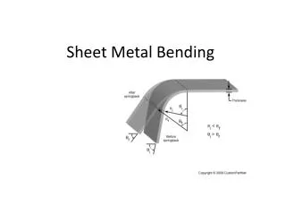
Selecting & Handling Tubing • Check for • Clean • No scratches or gouges • Out of round ends • Burr • Seams • Handling • Dragging • Capping • Uncoiling • Cutting • Tube Cutter • Sharp saw • Cutting wheel • deburr
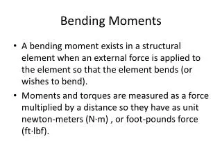
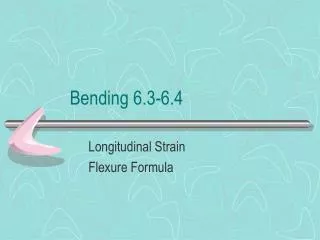
Tube Installation Bend Allowance T - Tube OD R – Bend Radius L - Length of straight tube required
Layout Sequential Layout Example 3 in. 3 in.
Sequential Bend Method Add the lengths or all section together to estimate the overall length of tubing required for the job. Mark the starting point (reference mark) for your project. Remember to make all marks completely around the tube. Measure from the reference mark to the vertex of the first bend. The vertex is the point where the center lines of the two legs of the angle meet. Bend the tube. Using the vertex of the previous bend as the reference mark, mark the vertex for the next bend the next bend. Repeat steps 3 and 4 for the next bend Layout
Sequential Layout 3 in. Vertex Reference Mark 3 in. Vertex 3 in. • Add the lengths or all section together to calculate the overall length of tubing required for the job.
Sequential Layout Reference Mark • Mark the starting point (reference market) for your project. Remember to make all marks completely around the tube.
Sequential Layout Reference Mark 3 in. Vertex • Measure from the reference mark to the vertex of the first bend. The vertex is the point where the center lines of the two legs of the angle meet.
90° Bends – Reference Left Reference Mark Align Vertex Mark With “L”
Sequential Layout • Bend the tube.
90° Bends – Reference Left Bend until 90 meets 0 Reference Mark
Layout Vertex New Reference 3in. Vertex • Measure and mark the next segment.
Sequential Layout Tip – Mark the vertex of the next bend to help alignment
45° Bends 30° Alignment Vertex 1 Vertex Mark
45° Bends Bend until 45 meets 0
Sequential Layout Vertex Bend the tube
Layout Calculations Offset Calculations 3.5 ? 3.5 x 1.414 = 4.494 or approx. 5 in.
Layout Calculations Offset Calculations
Layout Calculations Offset Calculations 3.5 5 Solution 3.50 x 1.414 = 4.949 or approx. 5 in.
Layout Calculations Adjustment (Gain) Calculations Reference Mark 1/4 in. OD Tubing 3 in. 3.5 in. Original Calculation 11 1/2 in. 3 in.
Layout Calculations Adjustment (Gain) Calculations
Layout Calculations Reference Mark Adjustment (Gain) Calculations 3 in. 3 in. + 3.5 in. – 5/16 in. = 6 3/16 in. 6 3/16 in. 3.5 in. 3in. New Calculation 9 1/2 in. – (2 x 5/16) = 8 7/8 in. in. 6 3/16 in. + 3 in. – 5/16 in. = 8 7/8
Bends Greater than 90° Bend until 0 meets 180, then a little more for spring back
Right Reference Bends Reference Mark 3 in. 3 in. 9 in. Tubing 3 in.
Reference Right Bends Align Vertex Markwith R
Changing Planes Plane 2 90° 90° Plane 1
Multi-Plane Bends 30° x 30° 2 1/2 in. 90° 2 1/2 in. 4 in. 2 1/2 in.
Multi-Plane Bends 0° 15° 15° 30° 30° 45° 45° 60° 60° 75° 75° 90° 90° Bend Direction
Multi-Plane Bends 0° 15° 15° 30° 30° 45° 45° 60° Bend Direction 60° 75° 75° 90° 90°
Multi-Plane Bends 0° 15° 15° 30° 30° 45° 45° 60° 60° 75° 75° 90° 90°
Multi-Plane Bends 0° 15° 15° 30° 30° 45° 45° 60° 60° 75° 75° 90° 90°
Imperfect Bends Common causes of imperfect bends Sometimes produced when thin wall tube is bent without a support mandrel. • May be caused by: • Not having the mandrel forward far enough in the tube • Bending thin wall tubes without a mandrel • Trying to bend too short a radius • Bending smaller diameter tubing in a larger radius block. May be caused by the tube slipping in the bender. A kinked bend may also result from the use of non-annealed tubing.
Installing Tube Runs • Avoid creating ladders • Run tubing close to the wall • Use support hangers every 3 – 5 ft. • Support valves, transmitters etc, independent of the tubing • Run tubing vertically when possible
Installing Tube Runs Stagger Connections