Download
1 / 24
860 likes | 2.05k Vues
2-D STRESS ANALYSIS. Introduction to 2-D Stress Analysis 2D and 3D Stresses and Strains von Mises and Tresca Yield Criteria 2-D Stress and Strain Results in NASTRAN. Introduction to 2-D Stress Analysis.

E N D
2-D STRESS ANALYSIS • Introduction to 2-D Stress Analysis • 2D and 3D Stresses and Strains • von Mises and Tresca Yield Criteria • 2-D Stress and Strain Results in NASTRAN
Introduction to 2-D Stress Analysis Up until now, we have only used rod shaped structural finite elements. These elements have been used to model framed or articulated structures such as trusses and frames. We are now going to begin working with two dimensional (planar) triangular (3 noded) or quadrilateral (4 noded) elements defined in a two dimensional plane to model 2-D dimensional elastic solid mechanisms and structures.
Tension member Introduction to 2-D Stress Analysis Question: Why 2-D Stress Analysis? Answer: In complex shaped structural or machine components stress concentration effects are often important factors that must be considered in the design process Note: A 1-D Beam or Truss (rod) analysis of the tension member shown below ignores the stress concentration in the fillet section and at the hole.
Introduction to 2-D Elastic Stress Analysis Two-dimensional stress analysis allows the engineer to determine detailed information concerning deformation, stress and strain, within a complex shaped two-dimensional elastic body. Assumptions • Deformations and strains are very small • Material behaves elastically – stress and strain are related by Hooke’s Law. • Hooke’s Law is a matrix equation relating 3 normal stresses and one shear stress to 3 normal strains and one shear strain
Modeled as Introduction to 2-D Elastic Stress Analysis 2-D Stress analysis allows the engineer to model complex 2-D elastic bodies by discretizing the geometry with a mesh of finite elements.
z Each node displaces in x and z direction Applied loading – generates deformation and stresses 4 3 1 u2z 2 u2x x Introduction to 2-D Stress Analysis Each finite element will deform because of the applied loading and boundary conditions on the body.
P’ uz ux P Introduction to 2-D Stress Analysis Every point within the element may translate in the x and z direction P(x,z) -> P’(x+ux, z+uz) z Note: ux and uz: x- and z-displacements are bi-linear functions of x and z. where a0, a1,.. b3 are unknown constants x
Introduction to 2-D Stress Analysis In 1-D analysis assuming small displacements and elastic material behavior we have: • A strain-displacement eqn., and, b) a stress-strain eqn. (1D Hooke’s Law) Question: What is the 2D or 3D form of these equations?
z z z x x x 2-D Strain-Displacement Equations There are two normal strains and : and one shear strain : Below are examples of simple constant strain states where onlyonestrain component is non-zero!
P’ uz ux P 2-D Strain-displacement Equations Question: What are the variations of the strain components for a element where the displacement field is defined by: ? z Note: ux and uz: x- and z-displacements are bi-linear functions of x and z. where a0, a1,.. b3 are unknown constants x
y σy σz σx σx x z σz σy 3D Isotropic Stress/Strain Law Three-dimensional Hooke’s Law: stress/strain relationships for an isotropic material As you recall, an isotropic body can have normal stresses acting on each surface: σx, σy, σz When the only normal stress is σx this causes a strain along the x- axis according to Hooke’s Law
3D Isotropic Stress/Strain Law Note, that a tensile stress in the x direction, produces a negative strains in the y and z directions This is called the Poisson effect. These negative strains are computed via: where: E is Young’s Modulus ν is Poisson’s ratio
3D Isotropic Stress/Strain Law Since the material is isotropic, application of normal stresses in the x, y, and z directions generates, a total normal strain in the x direction: + +
3D Isotropic Stress/Strain Law The total normal strains in the y and z directions can be determined in a similar manner:
3D Isotropic Stress/Strain Law Rearranging the above equations and yields 3 equations relating normal stresses and strains : These equations can also be written in matrix notation: {σ}=[D]{ε}
σy σz τyx y σx σx τxy σz σy x z Shear Stress/Strain Relationships Hooke’s law also applies for shear stress and strain: τ=Gγ where G is the shear modulus, τ is a shear stress, and γ is a shear strain. For 3-D this results in a further 3 equations.
Plane Stress Plane Strain Axisymmetric Introduction to 2-D Stress Analysis 2-D planar elements are used to model complex 2-D geometries. They must connect at common nodes to form continuous structures. They are extremely important in the following analysis types:
Plane Stress Plane Stress, in NASTRAN, is defined to be a state of stress in which the normal and shear stresses perpendicular to the x-z plane are zero, the y-thickness is very small, and the constraints (TX,TZ) and loads act only in the x-z plane and throughout the y-thickness. • σy = 0 • τxy= 0, τyz=0 • ‘thickness’, y dimension, is very small compared to x and z dimensions • Loads act only in the x-z plane and throughout the y-thickness z F3 F1 x y
Plane Strain Plane Strain, in NASTRAN, is defined to be a state of strain in which the normal strain in the y-direction, εy and the shear strains, γxy and γyz are zero. Note, the y-thickness of the body is very large, and constraints and loads act in x-z plane throughout thickness. • The ‘thickness’, y-dimension of the body is very large (“infinite”). Note, the NASTRAN finite element model analyzes only a ‘unit’ thickness • Loads and constraints act only in the x-z plane through a unit y-thickness • Forces are defined as force per unit y-length • A plane stress state, where y is a very large value, does not approximate plane strain conditions! • εy = 0, γxy= 0, γyz =0 z x y
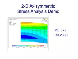
z x q Axisymmetric Analysis Axisymmetric conditions exist when the problem geometry is such that the z-axis is an axis of symmetry, and the displacement is radially symmetric (independent of q). In this case the only non-zero shear strain, is γxz. Note, that loads and constraints act over a ring defined by 0 < q <2p in the x-z plane. The only shear strain that is non-zero is γxz A ‘thickness’of 1 radian in the q direction around the z-axis is modeled by NASTRAN
von-Mises Stress A stress quantity that is proportional to the the strain energy density associated with a change in shape (with a zero volume change) at a material point is the von-Mises stress which is defined by: NOTE: the von-Mises stress is a scalar measure of the stress state (the normal and shear stresses) at any point within a body
von Mises Yield Criterion The von Mises criterion is an experimentally based law that can be used to determine whether the stress state in a material causes plastic flow (or yielding). Note, the von Mises criterion is based on the strain energy density associated with a change in shape (with a zero volume change) at a material point. The criterion simply states that when: the material point is elastic the material point is yielding
Tresca Yield Criterion Tresca yield criterion is another material model which may be used to determines whether a stress state in a material causes yielding. The criterion simply states that when: the material point is elastic the material point is yielding
2D Stress Analysis Results in NASTRAN After analyzing an NASTRAN model, results in superview can be found: • With displacement just as we did with beam and truss models • In results von Mises • In results Stress tensor Global Based • yy is the normal stress in y direction • zz is the normal stress in the z direction • yz is the in-plane shear stress