Download
1 / 4
40 likes | 139 Vues
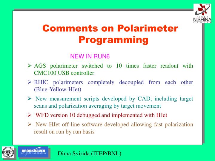
Comments on Polarimeter Programming NEW IN RUN6 AGS polarimeter switched to 10 times faster readout with CMC100 USB controller RHIC polarimeters completely decoupled from each other (Blue-Yellow-HJet)

E N D
Comments on Polarimeter Programming NEW IN RUN6 • AGS polarimeter switched to 10 times faster readout with CMC100 USB controller • RHIC polarimeters completely decoupled from each other (Blue-Yellow-HJet) • New measurement scripts developed by CAD, including target scans and polarization averaging by target movement • WFD version 10 debugged and implemented with HJet • New HJet off-line software developed allowing fast polarization result on run by run basis
New in WFD Version 10 • Data flows and calculation algorithms are significantly changed • No direct readout – only storage of events to the onboard memory • Raw waveform modes completely removed (now HJET, AT, ALL) • HJet waveform mode introduced allowing prehistory recording and programmable waveform length up to 3.5 s • New baseline subtraction algorithm introduced: • 4 points of each “no signal” waveform are averaged within the window of the bunch period • “running average” over 64 “no signal” bunches calculated • the baseline of the inverted signal is shifted 8 ADC units from zero to account for the noise and small overshoot • Separate waveform and parameters FIFO allow buffering in all modes of operation including ‘ALL’ (waveform+parameters) • Lookup tables, histograms and scales are kept the same as in V9 for fast on-line result To waveform recorder Level trigger Baseline subtraction, inversion and shift ADCs 3pt filter Baseline calc
Data Flows in V10 ‘HJET’ MODE Length Delay Level trigger To memory Digital delay line Gate Waveform FIFO ‘AT’ AND ‘ALL’ MODES WF enable Gate ‘WF’ FIFO Delay 2 bunch crossings To memory ‘AT’ FIFO TMAX, Amplitude, Integral Delay 1 bunch LUT logic Histograms Backward scan Time algorithms • Completely different data flows in different modes, yet sharing the same FPGA resources
Time Determination Algorithms • Based on previous test signal off-line calculations 2 best time algorithms were chosen out of 7 studied • Programmable CFD threshold ¼ or ½ of the amplitude CFD 3+3 points • 3 points above and below threshold are averaged • Line connecting averages crossing the threshold defines the time Average leading edge • Area of the hatched figure is calculated and divided by the amplitude • The time is represented by the horizontal side of the equivalent rectangular