Download
1 / 57
570 likes | 694 Vues
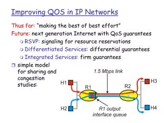
9.1. Introduction The current Internet: IP Protocol Best-Effort Service – no Quality of Service (QoS) guarantees are provided.

E N D
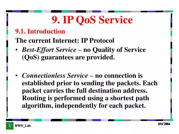
9.1. Introduction The current Internet: IP Protocol Best-Effort Service – no Quality of Service (QoS) guarantees are provided. Connectionless Service – no connection is established prior to sending the packets. Each packet carries the full destination address. Routing is performed using a shortest path algorithm, independently for each packet. 9. IP QoS Service
Why do we need a new protocol ? The emerging Multimedia applications require QoS guarantees. Real-time applications require connection oriented services. Other routing algorithms may be more appropriate than the shortest path algorithm in order to increase network efficiency and provide QoS.
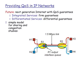
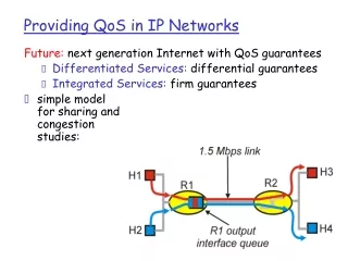
IETF* proposed solutions: Integrated Services (IntServ) Resource Reservation Protocol (RSVP) Disadvantage: Scalability (per-flow reservations) Differentiated Services (DiffServ) Disadvantage: No per-flow QoS guarantee Multiprotocol Label Switching (MPLS) *IETF – Internet Engineering Task Force
A network is characterized as having EDGE and CORE ROUTERS. Edge routers accept customer traffic, i.e., packets from any source outside the network into the network. Core routers provide transit packet forwarding service between other Core routers and/or Edge routers. Edge routers characterize, police, and mark customer traffic being admitted to the network. Edge routers may decline requests signaled by outside sources (Admission Control). Core routers differentiate traffic insofar as necessary to cope with transient congestion within the network itself. Statistical multiplexing must be utilized wherever appropriate to maximize utilizaton of core resources. REQUIREMENTS for IP QoS
IntServ developed an architecture requiring per-flow traffic handling at every hop along an application’s end-to-end path and explicit a priori signaling using RSVP (Resource Reservation Protocol) of each flow’s requirements. IntServ model requires resources such as bandwidth and buffers to be explicitly reserved for a given data flow to ensure that the application receives its requested QoS. A flow is composed by a stream of packets with the same source and destination addresses and port numbers. A flow descriptor is used to describe the traffic and QoS requirements of a flow. 9.2. Integrated Services (IntServ)GOAL: Augment existing Best Effort Internet with a range of end-to-end services for real-time streaming in interactive applications.
Per-flow QoS guarantees are provided at the expense of installing and maintaining flow-specific state in each router along the flow’s path. Basic components of the IntServ architecture: Setup Protocol, Traffic Control (filterspec), flowspec and Traffic Classes.
Setup Protocol – enables a host or an application to request a specific amount of resources from the network realized by (Resource Reservation Protocol (RSVP)) Traffic Control (filterspec) – includes packet classifier, packet scheduler, and admission control. flowspec – objects such as token bucket parameters. Traffic Classes – best-effort, controlled load, and guaranteed services. 9.2.1.Architecture Basic Components
Every application is presumed to use some form of signaling to negotiate service with an IntServ capable network. IntServ signaling has 2 functions: Negotiation: When the network decides whether it can support the applications requested service (Admission Control) Configuration: When the network configures the routers along the path to support the negotiated flow characteristics. The applications use RSVP: Resource Reservation Protocol. 9.2.2. Setup Protocol: RSVP
Goals for the Design of RSVP: Must support both unicast and multicast traffic flows (i.e., RSVP sessions). Must allow parties of a multicast session to request different levels of QoS. Must be deployable on top of existing IP infrastructure.
Basics of RSVP: Performs resource reservations for unicast and multicast applications. Requests resources in one direction from a sender to a receiver (simplex resource reservation) Requires the receiver to initiate and maintain the resource reservation. Maintains soft state at each intermediate router: A resource reservation at a router is maintained for a limited time only, and so the sender must periodically refresh its reservation. Does not require each router to be RSVP capable. Non-RSVP capable routers use Best Effort delivery technique. Provides different reservation styles so that requests may be merged in several ways according to the applications. Supports both IPv4 and IPv6.
Similar to “Leaf Join Case” in ATM Multicasting. Motivation: RSVP is primarily designed to support multiparty conferencing with heterogeneous receivers. In this environment the receiver actually knows how much bandwidth it needs. If the sender were to make the reservation request, then the sender must obtain the bandwidth requirement from each receiver. This may cause an implosion problem for large multicast groups. Problem:Receiver does not directly know the path taken by data packets. Solution:Use Path messages. RSVP: Receiver Initiated Reservation
The application source transmits a “Path” message along the routed path to the unicast or multicast destination. The Path message has two purposes: * to mark the routed path in each router (store the “path state”) between sender/receiver and * to collect information about the QoS viability of each router along that path. Upon receiving the Path message, the destination host(s) can determine what services the network can support (e.g., guaranteed service or controlled load) and then generate an RSVP reservation (Resv) message. RSVP
Resv messages are sent back towards the sender along the reverse path. The Resv message carries reservation requests to the routers along the path. The Resv message contains traffic and QoS objects that are processed by the traffic control component of each router as it follows the reverse path upstream toward the sender. If the router has sufficient capacity, then resources along the path back towards the receiver are reserved for that flow. If resources are not available, RSVP error messages are generated and returned to the receiver.
SOFT STATE in RSVP RSVP Path and Resv messages are periodically sent by senders and receivers, respectively, to refresh the reservations performed. When a state is not refreshed within a certain time out, the state is deleted. The type of state that is maintained by a timer is called “Soft State” as opposed to hard state where the establishment and teardown of a state are explicitly controlled by signaling messages.
RESERVATION STYLES in RSVP Wildcard Filter Reservation A single reservation shared by all senders. Kind of shared pipe whose resource is the largest of the resource requests from all receivers, independent of the number of senders. (e.g., Audioconferencing). Fixed FilterReservation A distinct reservation is created for each sender. S_i is the selected sender and Q_i is the resource request for sender i. The total reservation on a link for a given session is the sum of all Q_i’s. Shared ExplicitReservation A single reservation shared by a set of explicit senders where S_i is the selected sender and Q is the flowspec.
flowspec is used to set parameters in the router’s packet scheduler. flowspec(Flow Specification) consists of traffic specification (Tspec)(T for traffic) and a service request specification(Rspec) (R for reserve). Tspec describes the sender’s traffic characteristics, i.e., it specifies the traffic behavior of the flow in terms of a token bucket. Rspec reserves a service class whichdefines the requested QoS, i.e., itspecifies the requested QoS in terms of bandwidth, packet delay or packet loss. flowspec is carried by RSVP messages into the network and defines the application’s QoS requirements as a series of objects, such as token bucket parameters. 9.2.3. Flow Specification (flowspec)An RSVP reservation request consists of flowspec and filterspec.
Classifier - examines the source and destination addresses, and port number fields in each packet to determine what class the packet belongs to. Scheduler - determines which packet will be served next. Admission Control - determines whether a new flow can be granted the requested QoS without affecting other flows existing in the network. 9.2.3. Traffic Control Components (filterspec) filterspec (Filter Specification) provides the information required by the packet classifier to identify the packets that belong to the flow.
Best-Effort - same as in the traditional IP networks. Controlled Load - approximates a best-effort over an uncongested network. Guaranteed Service - supports real-time traffic flows that require a delay bound. 9.2.5. Traffic Classes Components
Under CL service, the packets of a given flow will experience loss and delays comparable to a network with a light traffic load, assuming the flow complies with the traffic contract. No guarantees are provided but both loss probability and delay are expected to be very low. The application provides the network with an estimate of the traffic it will generate. This estimate is done by specifying the data flow’s desired traffic parameters (Tspec) to the network element. Controlled Load Service
Tspec (Traffic Specification) Model: It is a refinement of the Token Bucket model. A source characterizes itself with the following SENDER-Tspec (traffic characteristics) parameters: * Token bucket rate r (bytes/sec) and size b (bytes) * Peak data rate p * Minimum policed unit m * Maximum packet size M Controlled Load Service
Admission Control is performed in order to deliver the expected QoS. Traffic flows are policed. Non-conformant packets are either dropped or delivered when possible using the best-effort service. Packets larger than the agreed maximum packet size will also be considered as nonconformant. Adaptive real-time applications are supposed to use the controlled load service. These applications perform well when the network is not heavily loaded, but suffer rapid degradation in performance as the network load increases. Controlled Load Service
GS guarantees the packets will arrive within a certain delivery time, and that they will not be discarded due to queue overflow, provided that the flow’s traffic complies with the traffic contract. GS also uses the Tspec model. The service is requested by a sender specifying Tspec and the receiver subsequently requesting a desired service level (Rspec). Guaranteed Service
Rspec (Reservation Specification) Model: Works together with the Tspec model to guarantee a desired service level. The desired service level is described using the following parameters (R data rate and S slack term) in addition to r,b,p,m and M used for CL service: Data rate R is measured in the same units as r and must be equal to or more than r (token rate). R reflects the theoretical service rate that, at each router, will result in a desirable delay bound. Slack term S is measured in microsec and reflects how far each router is allowed to deviate from the ideal delay bound, i.e., the difference between the desired delay and the delay obtained by using a reservation level R. REMARK: Larger values for R and smaller values for S represent stricter delay bounds. Guaranteed Service
Making use of TSpec and RSpec, a certain amount of bandwidth and buffer space is allocated at each node for each flow. Resources are allocated using worst-case analysis. Upper bounds for the end-to-end delay and the packet loss probability can be evaluated mathematically. Guaranteed Service
Sources emit regular PATH messages downstream toward the receiver(s) for reservation Two message objects relevant to IntServ are carried in PATH messages: SENDER_Tspec (describing the traffic) and ADspec (modified at each hop to reflect the network characteristics between source and receiver). ADspec informs the receiver which service classes (CL, GS or both) are appropriate for the traffic. Along the way, IntServ capable routers may modify the ADspec relevant to reflect restrictions or modifications required by the network. SIGNALING and ADMISSION CONTROL
Receiver(s) respond with Resv messages upstream toward the sender Receiver uses the SENDER_Tspec and (possibly modified) ADspec to determine which parameters to send back upstream in a flowspec element. flowspec selects either CL or GS and carries parameters required by the routers along the upstream path to determine whether the request can be honored or not. One message object relevant to IntServ is carried in Resv messages: flowspec (describing the receiver’s desired QoS service to be applied to the sources’ traffic). SIGNALING and ADMISSION CONTROL
Scalability– per flow resources reservation. Flexibility– IntServ provides a small number of pre-specified traffic classes: Guaranteed and Controlled Load Services. Efficiency – The Guaranteed Service of the IntServ model is based on the worst case analysis and thus, is very conservative. Moreover, bandwidth and delay requirements are coupled, causing network inefficiency. 9.2.6. IntServ Drawbacks
Complicated RSVP signaling (unidirectional, frequent refresh messages). The current version of RSVP lacks both adequate security mechanisms to prevent unauthorized parties from instigating theft-of-service attacks, and policy control. Resource Reservation ProtocolDrawbacks
Because of the difficulty in implementing and deploying IntServ and RSVP, the IETF proposed the Differentiated Services (DiffServ) architecture, the current most promising approach to support IP QoS. Looking for a New Solution…
Solves scalability and flexibility problems: Forces as much complexity as possible to the edge nodes which process lower volumes of traffic and lesser number of flows. Offers service per aggregate traffic, rather than per flow. Reservations are made for a set of related flows. It does not require new applications or extensive router upgrades. It does not define specific services or service classes, as IntServ does. 9.3. Differentiated Services (DiffServ)
The objective of the DiffServ working group is to propose a small, well-defined set of building blocks from which a variety of services may be constructed. Complexity is moved from the core of the network to the edge of the network. Packet forwarding in the core network is simple and per-aggregate rather than per-flow. Differentiated Services
The DS byte is used to specify the forwarding treatment (or per-hop behavior) to be used for a packet. Differentiated Services The DSCP (DiffServ Code Point) byte is used to specify the forwarding treatment (or per-hop behavior) to be used for packets The DS byte coincides with the TOS octet in IPv4 and the Traffic Class octet in IPv6.
A DiffServ Domain is a set of contiguous DS nodes defining the same per hop behaviors (PHBs) and under the same policy strategy. A DS domain consists of DS interior, edge, and boundary nodes. A boundary node interconnects the DS domain to other DS or non-DS-complaint nodes. Edge and interior nodes only connect to other interior, edge, or boundary nodes within the same DS domain. Differentiated Services
Edge nodes handle a relatively small number of traffic flows. Therefore, they can execute per-flow traffic management. Edge nodes are responsible for policing and shaping. They are also responsible for admission control, if any. Core nodes handle a large amount of traffic flows. They perform per-aggregate rather than per-flow traffic management. 9.3.1. Edge and Core Nodes
Traffic Classification consists in assigning every packet in a traffic stream to a defined traffic class. A Traffic Profile specifies the temporal properties of a traffic stream selected by a classifier, providing rules for determining whether a particular packet is in-profile or out-of-profile. Traffic Conditioning is usually executed by the boundary nodes. 9.3.2. Traffic Classification and Conditioning
Meter: A meter measures the temporal properties of the stream of packets selected by the classifier against a traffic profile. Marker: A packet is marked by setting its DS field to a particular codepoint. The packet now belong to a certain behavior aggregate. Shaper: A shaper holds (delays) some or all the packets in a traffic stream to make the stream to become compliant to the traffic profile. Dropper: A dropper discards some or all the packets in a traffic stream to bring the stream into compliance with the traffic profile. Meter Shaper/Dropper Classifier Marker Packets 9.3.3. Traffic Conditioning Components
The PHB defines the service a packet receives at each hop as it is forwarded through the network. It is realized through internal queue management and scheduling techniques. 5 bits of the DS byte can be used to specify the PHB. Therefore, (2^5) = 32 PHBs can be defined. The IETF intends to standardize only a few of them. Packets marked with different DS byte values should receive different PHB and, accordingly, should experience different services in the core network. Services can be differentiated using appropriate Scheduling Queue Management 9.3.4. Per-Hop Behavior
Different output queues are used for different PHBs. Queues can be served according to Strict priority queuing Weighted Round Robin Weighted Fair Queuing Virtual Clock 9.3.5. Scheduling
When a router runs out of buffer space packets must be dropped. In DiffServ, dropping decisions take the DS byte value into account. For example if Weighted Random Early Detection (WRED) is used: 9.3.6. Buffer Management
The IETF DiffServ Working Group is finishing work on two PHBs: Expedited Forwarding (EF) Assured Forwarding (AF) 9.3.7. IETF Per-Hop Behaviors
The EF PHB was designed to support low loss, low delay, and low jitter connections. It appears as a point-to-point virtual leased line (VLL) service between endpoints with a peak bandwidth. To minimize jitter and delay, packets must spend little or no time in router queues. Therefore, the EF PHB requires that the traffic be conditioned to conform to the peak rate at the boundary, and the network of routers be provisioned such that this peak rate is less than the minimum packet departure rate at each router in the network. The EF PHB uses a single DSCP bit to indicate that the packet should be placed in a high-priority queue on the outbound link of each router hop. Expedited Forwarding PHB
The AF PHB defines four relative classes of service with each service supporting three levels of drop precedence. Twelve distinct DSCP bit combinations define the AF classes and the drop precedence within each class. When congestion is encountered at a router, packets with a higher drop precedence will be discarded ahead of those with a lower drop precedence. The four AF classes define no specific bandwidth or delay constrains other than that AF class 1 is distinct from AF class 2, and so on. Assured Forwarding PHB
The QoS enjoyed by a flow is dependent on the behavior of the other flows belonging to the same aggregate. There is no per-flow guarantees. 9.3.8. DiffServ Drawbacks
MPLS is a forwarding paradigm. Choosing the next hop can be thought as the composition of two functions: Partitioning the entire set of possible packets into a set of Forwarding Equivalence Classes (FECs). Mapping each FEC to a next hop. In the Multiprotocol Label Switching (MPLS), the assignment of a packet to a particular FEC is done just once: when the packet enters the network. 9.4. Multiprotocol Label Switching (MPLS)
The FEC is encoded as a short fixed length value called label. When a packet is forwarded to its next hop, the label is sent along with it. At subsequent hops, there is no further analysis of the packet network layer header. The label is used as an index into a table which specifies the next hop and a new label. The old label is replaced with the new label and the packet is forwarded to its next hop. Multiprotocol Label Switching
Some routers analyze a packet’s network layer header also to determine a precedence or class of service. They may then apply different discard thresholds or scheduling disciplines to different packets. MPLS allows (but does not require) precedence or class of service to be fully or partially inferred from the label. In this case, the label represents the combination of a FEC and a precedence or class of service. 9.4.1. Service Classes
The architecture of the Internet can be broken into four basic layers: Physical Layer Link Layer Network Layer Transport Layer. The OSI models has three more layers on top of the transport layer. MPLS is between the link and the network layer (2.5 layer). 9.4.2. The Internet Architecture
MPLS forwarding must simplify packet forwarding with the following objectives: Lower cost of high speed forwarding. Improve forwarding performance. MPLS core technologies must be general with respect to data link technologies. Specific optimizations for particular media may be considered. MPLS core technologies must be compatible with a wide range of routing protocols, and must be capable of operating independently of the underlying routing protocols. MPLS must provide protocol mechanisms to either prevent the formation of loops and/or contain the amount of resources that can be consumed due to the presence of loops. 9.4.3. Requirements
MPLS must allow aggregate forwarding of user data. MPLS should provide multiple levels of aggregation support. MPLS must support operation, administration, and maintenance facilities at least as extensive as those supported in current IP networks. MPLS core technologies must work with both unicast and multicast streams. Scalability issues must be considered and analyzed. The MPLS protocol standards must support multipath routing and forwarding. MPLS must be compatible with the IETF Integrated Services Model, including RSVP. MPLS switch must coexist with existing non MPLS switch in the same switched network.