Download
1 / 29
310 likes | 498 Vues
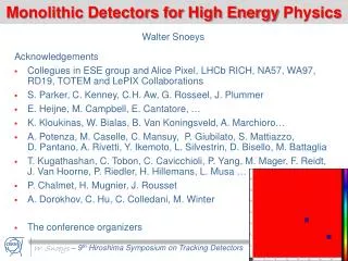
Monolithic Integration of Detectors and Transistors on High-Resistivity Silicon. G.-F. Dalla Betta 1 , G. Batignani 2 , L. Bosisio 3 , M. Boscardin 4 , P. Gregori 4 , C. Piemonte 4 , L. Ratti 5 , G. Verzellesi 6 , N. Zorzi 4. 1 INFN Trento and University of Trento,Italy

E N D
Monolithic Integration of Detectors and Transistors on High-Resistivity Silicon G.-F. Dalla Betta1, G. Batignani2, L. Bosisio3, M. Boscardin4, P. Gregori4, C. Piemonte4, L. Ratti5, G. Verzellesi6, N. Zorzi4 1 INFN Trento and University of Trento,Italy 2 INFN Pisa and University of Pisa, Italy 3 INFN Trieste and University of Trieste, Italy 4 ITC-irst,Trento, Italy 5 INFN Pavia and University of Pavia, Italy 6 INFN Trento and University of Modena/Reggio Emilia, Italy
Outline • Introduction • Process development at ITC-irst • Transistor description: • Experimental results • Conclusions n-JFET (tetrode, triode) n-MOSFET npn BJT
Introduction • Front-end electronics embedded on the detector substrate • can provide better noise performance and easier assembly, • at the expense of process complexity and cost • Normally worth for low capacitance detectors only • Pioneering work in this field dates back to late 80’s: • MPI Munich & BNL (for drift detectors), • LBNL (detector compatible CMOS process for pixels) • Most successful developments: fully depleted CCDs and • DEPFET talk by J.Velthius
Process development at ITC-irst • It all started as a major technological challenge: first step • toward becoming a primary technological partner for INFN • The process development went on in the framework of few • national projects (INFN and MIUR), mainly device oriented • When device performance improved, we could start to • identify suitable applications • Current activity is oriented to: • g-ray scintimammography (PIN diode + tetrode JFET) • X-ray imaging (JFET-MOSFET active pixels) • Radon monitoring (BJT)
Fabrication technology overview • Starting material: HR Si, 4”, <111>, n-type • P-doped poly-Si gettering (back-side) • Deep implantations (p-well, n-channel) • Active area & poly-Si (low- and high-doping) • Shallow implantations • Interconnections (metal 1, metal 2) Standard steps Dedicated steps
2 options (different doping profiles) p+ n+ p+ p+ n+ n+ n-channel p-well p-well n- Si substrate b) BJT (by product) a) JFET n- sub. n- sub. p+ n-ch. p-well n+/n-ch. p-well Base Collector Top-gate Bottom-gate Emitter
Process parameters Data from last batch (JSD6, 2006) Diode leakage current (thickness=300mm) Additional steps do not degrade the process quality
Transistors: tetrode n-JFETs Enclosed layout drain source Bottom-gate 100/6 Top-gate (Lmin=6mm): it needs contact on top-gate
Tetrode JFET (W/L=100mm/6mm) Allows for independent top-gate and bottom-gate control Transfer characteristics in saturation region (Vds=3V) Top-gate modulation Bottom-gate modulation
Tetrode JFET (W/L=100mm/6mm) Output characteristics (Vbg=0) Input capacitance (Vbg=0) Low capacitance can match small area detectors
Detector head for scintimammography Back side: CsI(Tl) scintillator + ARC 99mTc g-rays (140keV) CsI(Tl) scintillator 550nm photons PIN detector ~2000 electrons Modular design tile Front side: 8x8 PIN+JFET array (pitch 2mm) Tetrode JFET as CSA input transistor 1.6 cm 8x8 PIN+JFET matrix 1.6 cm Bump bonding to ASICs via LTCC interconnection
Transistors: triode n-JFETs 1000/4 Stripe interdigitated layout (Lmin=4mm) gate Top-gate & Bottom-gate shorted at the implant level drain source
Triode JFET (W/L=1000mm/4mm) Transfer characteristics (Vds=3V) Input capacitance Due to bottom gate contribution, larger transconductance, but also larger capacitance (and gate current)
Triode JFET (W/L=1000mm/4mm) Noise spectrum (Vds=3V) White noise (Vds=3V) White noise close to theoretical value (normal RGG’), Very good low-frequency noise behavior
Benchmark: JFET-based CSA Monolithic part Equivalent Noise Charge (with 8th order semigaussian unipolar shaper) + external passive components Good ENC, in spite of large Cstray from the test board
Transistors: n-MOSFETs Enclosed layout (Lmin=4mm) 125/5 S&D self-aligned to poly-Si gate. gate well source drain
NMOS (W/L=125mm/5mm) Transfer characteristics (Vds=0.1V) Output characteristics Static characteristics are good enough to implement basic circuit functions
Example: current mirror GND D2 D1 Max. Error 7% Max. error 4% Vd2=3V
Fully integrated CSA 650 mm Bias/Feedback 900 mm JFETs
Active pixel arrays (1) On pixel (3T-like APS) • P-well/substrate detector • Punch-through Reset • Address: M1 • Source follower: J1 • Column pull-down: J2 • Readout: DDS stage
Active pixel arrays (2) 235 mm 4 mm Pixel J2 235 mm Pixel matrix 6 mm DDS RES M1 J1 Only one collecting electrode
Transistors: npn BJTs Two emitter profiles and different layouts possible Emitter area 0.01mm2 base emitter
Deep emitter npn BJT (AE=0.01mm2) Current gain (b) Very high gain (~600) allows for radiation detection with a simple setup (load resistor only) … Transient response … but it needs bias to obtain a time constant of ~ 10s of ms. Without bias
Vbias scope R L a particle counter • particles from 239Pu source (with 150 kW Rload) Rpoly~100MW (must be >>rbe) Interesting for Radon monitoring with an extremely simple setup
Conclusions • We have reported on recent results from the development of detector-compatible transistors at ITC-irst • Devices feature good characteristics that are promising in view of full detector system implementations • With last batch, we have started to focus on some applications • The prototype functional tests are under way • The technology is available to interested application-oriented partners
Radiation damage effects Single JFETs (1000/4) irradiated with neutrons Gate current (Vgs=0, Vds=3V) Noise spectrum (Id=250mA, Vds=3V) Increase of gate current (proportional to fluence) Lorentzian noise contributions appear
Irradiated CSA: ENC prediction Based on input JFET characteristics (1000/4) Minor effect of Lorentzian noise Large effect of gate current increase and related need of lower RF value Should be better with tetrode JFET (lower current from top-gate alone)
vcontr Epnp Cnpn Bpnp Enpn BJT biasing: pnp BJT Allows for multi-element current biasing (current mirror) x IR laser pulses @ different Vcontr (with 20kW Rload) bias region x