Download
1 / 51
510 likes | 615 Vues
WAN Technologies. Chapter 16. Chapter Objectives – I. Differentiate between the types of network switching Explain the Public Switched Telephone System Discuss the Mobile Telephone System Explain point-to-point WANs Describe the X.25 protocol. Chapter Objectives – II. Explain Frame Relay

E N D
WAN Technologies Chapter 16
Chapter Objectives – I • Differentiate between the types of network switching • Explain the Public Switched Telephone System • Discuss the Mobile Telephone System • Explain point-to-point WANs • Describe the X.25 protocol
Chapter Objectives – II Explain Frame Relay Explain ATM Explain the ISDN protocol and BISDN Explain the FDDI protocol Explain satellite communication
Recall – I • Router is an Internetworking device used to link two different networks • Two types of NAT are: • Static NAT • Dynamic NAT • Proxy server is a computer that allows network users to make an indirect network connection to different network services
Recall – II Types of proxies are: Transparent proxies Reverse proxies Anonymous proxies Zones of Internet explorer: Internet zone Local Intranet zone Trusted Sites zone Restricted Sites zone
Recall – III Applications of Internet: World Wide Web Electronic mail File Transfer Protocol TELNET
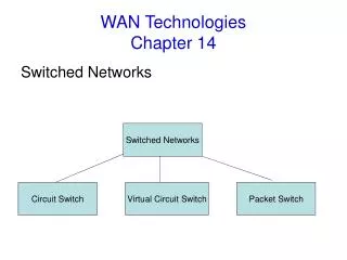
Types of Switching • Switching is a process of moving the data through a series of intermediate steps rather than moving from the start point directly to the end point.
Show all switching technique from CBT Circuit Switching Direct physical connection established between sender and receiver before data transmission Allows a fixed rate of transmission Major drawbacks are: Unused transmission is wasted Unused bandwidth cannot be used by any other transmission
Message Switching No direct physical connection established between sender and receiver Message routed through the intermediate nodes This technology is also known as store and forward method
Packet Switching Message to be transmitted broken into units called packets Packet contains addressing information Packets are carried on virtual circuits. Virtual circuits are temporary connections over which the sending and receiving stations communicate
Connectionless Services Before transmitting the packets, actual connection not established between the sender and the receiver Each packet considered as an independent unit Each packet treated as a complete message Packets follow different routes to reach destination
Connection-oriented Services Before transmitting packets, communication link established Packets follow same route to reach destination For transmission, uses either Switched Virtual Circuit (SVC) or Permanent Virtual Circuit (PVC)
Public Switched Telephone Network Telephone system that uses copper wires to carry analog voice data is called Public Switched Telephone Network (PSTN) Telephone services carried by the PSTN are often called as Plain Old Telephone Service (POTS). Services offered by POTS are follows: Bi-directional – full duplex Ringing signals and dial-tone Operator services Conference calling assistance Uses electromechanical switches and now a days it has been made digital
Structure of Telephone System – I Digital transmission is more reliable than analog and less prone to noise and interference and also it is cheaper and easier to maintain Telephone system consists of following major components: Local loops – Analog twisted pairs going into houses and businesses Switching offices – Place where the calls moved from one trunk to another Trunks – Switching offices connected using digital fiber optics called trunks
Structure of Telephone System – II Typical circuit route for a medium-distance call:
Structure of Telephone System – III and Local Loops Switching center is known as a toll office Different tolls communicate with each other using the high bandwidth intertoll trunks Local loop is sometimes referred to as last mile Uses analog signaling
Multiplexing Link is the physical path between sender and receiver whereas channel is the portion of a link that carries a transmission Three types of multiplexing: Time Division Multiplexing (TDM) – used for digital data Frequency Division Multiplexing (FDM) – Wavelength Division Multiplexing (WDM) – used for optical carrier signals
Mobile Telephone System Passed through three stages: First Generation (Analog voice) – known as cellular mobile radio telephone used in US advanced mobile phone system (AMPS) was launched commercially Second Generation (Digital Voice) – Uses FDMA, TDMA and CDMA technologies Third Generation (Digital Voice and Data) – intended for true multimedia cell phone called as smart phones Data Transfer Rate (DTR) is 3 Mbps
Point to Point WANs Two remote devices connected using a line available from a public network Public network can be a telephone network Services basically provided at the physical layer Users responsible for the data link layer protocols
Physical Layer To accomplish point-to-point connection between two devices at the physical layer, use the following services: Modem technology (56K Modem) Digital Subscriber Line (DSL) – uses existing telecommunication networks to achieve high speed bandwidth Cable modem T-line (digital) – T1 – 1.544 Mbps T3 – 44.736 Mbps E1 Lines (digital) – 2.048 Mbps SONET – 51.84 Mbps (ANSI)
Data Link Layer Concerned with data transfer Protocol needed for reliable connection A protocol is needed at this layer to have a reliable point-to-point connection. For reliability, uses Point-to-Point Protocol (PPP) For establishing, maintaining and terminating the link, uses Link Control Protocol (LCP) For providing flexibility to PPP, uses Network Control Protocol (NCP)
X.25 Protocol Connection-oriented packet-switching protocol at the network layer Defines the way in which the connections between the user devices and the network devices are established and maintained. Used in the packet-switched networks (PSNs) such as the telephone companies.
X.25 Devices - I X.25 network devices are: Data terminal equipment (DTE) Data circuit-terminating equipment (DCE) Packet-switching exchange (PSE)
X.25 Devices - II X.25 Session establishment – a full duplex communication is established between two devices and can be terminated by either of the two devices Packet Assembler/Disassembler (PAD) – main function is buffering and adds an X.25 header to the packet
X.25 Virtual Circuits - I X.25 virtual circuits are: Switched Virtual Circuits (SVCs) Permanent Virtual Circuits (PVCs)
X.25 Virtual Circuits - II Multiple virtual circuits also called as logical connectors Source DTE devices specifies the virtual circuits to be used in the headers of the outgoing data packets
Show from CBT Frame Relay High performance WAN protocol, faster than X.25 Operates at the physical and data link layer of the OSI reference model Does not involve error correction and network flow control operations Frame relay virtual circuits are: Switched Virtual Circuits (SVCs) Permanent Virtual Circuits (PVCs)
Frame Relay Devices The devices attached to the Frame Relay WAN for transmission of data packets are, Data terminal equipment (DTE) and Data circuit-terminating equipment (DCE).
Case Study – I The head office of the MoneyMaker bank in Mumbai is integrated with all its branches using the FDDI technology. All the transactions are carried out using this network. Due to congestion in the network the bank is losing critical data which has become a major area of concern for the bank.
Problem Data loss due to congestion in FDDI network technology.
Suggested Solution All the branches should be integrated using the Frame Relay technology. Frame Relay provides a congestion control mechanism.
Asynchronous Transfer Mode (ATM) Cell-switching and multiplexing technology which combines the benefits of both circuit switching and packet switching Transmits data, voice and video signals simultaneously over the same communication lines Before transmission, this information is converted into fixed size cells Cell consists of 53 octets or bytes Header information is contained in the first 5 bytes and 48 bytes contain user information
ATM Devices ATM network consists of two devices: ATM Switch ATM endpoint
ATM Network Interface Uses two types of interfaces for interconnection User Network Interface (UNI) Network to Network Interface (NNI) The UNI and NNI are classified on the basis of whether the switch is owned and located at the customer’s premises or are publicly owned and operated by the telephone company
ATM Reference Model Reference model comprises of the following: ATM layers ATM planes
Integrated Services Digital Network (ISDN) Involves digital telephony and data-transport services offered by the regional telephone carriers Permits transmission of voice, data, text, graphics, music and video over existing telephone lines Consists of following devices: Terminals Terminal Adapters Network Termination Devices
ISDN Services The information transmitted over the ISDN network travels through the three logical digital communication channels: B-Channel - Carries user service information that includes digital data, video and voice. It is the basic user channel and operates at 64 kbps D-Channel - Carries signals and data between the user and the network. H-Channel - Performs the same functions as that of the B-Channels and operates at data rate of 64 Kbps. ISDN BRI service – operates 192 kbps ISDN PRI service – operates at 1.544 mbps
Broadband ISDN (BISDN) Extension of ISDN Used for technologies such as video conferencing and file transfer and operates at 600 Mbps Provides two types of services as follows: Interactive Services Distributive Services
Case Study – II All the branches of MoneyMaker bank have to send daily transaction details to the Mumbai branch. The size of this file is very large. The bank uses a regular telephone line and a standard modem to send this file.
Problem Slow data transmission
Suggested Solution Setup an ISDN. Certain things are required to set up an ISDN service which includes, a ISDN modem or router, Service Profile Identifiers (SPIDs) from the telephone company, the name of the switch or the network type the phone company uses, and account information from the ISDN service provider.
Fiber Distributed Data Interface Based on ring topology and token passing Two optical fibers used as follows: Multimode optical fiber Single-mode optical fiber Two types of copper cables used as follows: Category 5 Unshielded Twisted Pair copper wiring IBM Type 1 Shielded Twisted Pair copper wiring
Use CBT Satellite Communication Two parts of satellite communication are: Uplink–Transmitter consisting of a ground-based part Transponder –The satellite-based part reflecting signals towards receivers Advantages: Satellites can cover large areas of earth I t is commercially attractive It is preferred instead of cables as maintenance of cables is expensive and difficult
Polling Communication technique which determines when a terminal is ready to send data Round robin sequence is used by the computer to continuously interrogate its connected terminals Communication system comprises of the following: A Master station Number of slave stations each communicating with the master station A two-way transmission line connecting the master station and the slave stations
ALOHA A simple communications scheme in which each transmitter or source in a network sends data whenever there is a frame to send is called as ALOHA Next frame sent only if the first frame reaches the destination successfully If the frame fails to reach the receiver, it is sent again Types of ALOHA: Pure aloha Slotted aloha
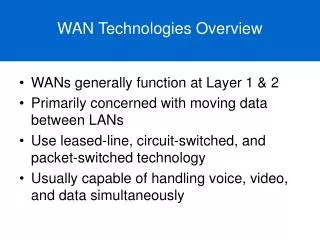
Summary - I • WAN covers a large geographical area and consists of two or more local area networks (LANs) • Circuit switching, message switching and packet switching are types of switching technologies used by WAN • Leased lines are the permanent point-to-point links used for data communication • Circuit switching networks establish a direct physical connection between a sender and a receiver before communication occurs
Summary – II In message switching, each switch stores the whole message and forwards it to the next switch Packet switching network transmits messages in the form of packets The telephone system that uses copper wires to carry analog voice data is called Public Switched Telephone Network (PSTN) Multiplexing is the technique that allows the simultaneous transmission of multiple signals across a single data link
Summary – III X.25 is a connection-oriented packet-switching protocol which was earlier used by the Internet Frame relay is a high performance WAN protocol which operates at the physical and data link layers and uses fiber optic cable and ISDN for digital data transmission ATM transmits data, voice and video signals simultaneously over the same communication lines ISDN digitizes the telephone network, to transmit the information over the existing telephone wires