Interconnecting Devices and Protocols in Computer Networks
310 likes | 330 Vues
Learn about the different types of interconnecting devices in computer networks, such as repeaters, hubs, bridges, switches, routers, and gateways. Understand the functions and advantages of these devices in extending network range and managing network traffic.

Interconnecting Devices and Protocols in Computer Networks
E N D
Presentation Transcript
Lecture 12 k.albasheir@psau.sa 3761 CS: Comp. Network System Interconnecting device protocol framing and error algorithm -PPP-MAC
Five connecting devices Repeaters Hubs Bridges Switches Routers Gateway Connecting Devices
A physical layer device the acts on bits not on frames or packets Can have two or more interfaces When a bit (0,1) arrives, the repeater receives it and regenerates it, the transmits it onto all other interfaces Used in LAN to connectcable segments and extend the maximum cable length extending the geographical LAN range Ethernet 10base5 – Max. segment length 500m – 4 repeaters (5 segments) are used to extend the cable to 2500m) Ethernet 10Base2- Max. segment length 185m - 4 repeaters (5 segments) are used to extend the cable to 925m Repeaters do not implement any access method If any two nodes on any two connected segments transmit at the same time collision will happen Repeaters
Acts on the physical layer Operate on bits rather than frames Also called multiport repeater Used to connect stations adapters in a physical star topology but logically bus Connection to the hub consists of two pairs of twisted pair wire one for transmission and the other for receiving. Hub receives a bit from an adapter and sends it to all the other adapters without implementing any access method. does not do filtering (forward a frame into a specific destination or drop it) just it copy the received frame onto all other links The entire hub forms a single collision domain, and a single Broadcast domain Collision domain: is that part of the network (set of NICs) when two or more nodes transmit at the same time collision will happen. Broadcast domain: is that part of the network (set of NIC) where each NIC can 'see' other NICs' traffic broadcast messages. Multiple Hubs can be used to extend the network length For 10BaseT and 100BaseT the maximum length of the connection between an adapter and the hub is 100 meters the maximum length between any two nodes is 200 m = maximum network length Hubs
Backbone hub interconnects LAN segments Advantage: Extends max distance between nodes Disadvantages Individual segment collision domains become one large collision domain (reduce the performance) Can’t interconnect different Ethernet technologies(like 10BaseT & 100BaseT) because no buffering at the hub Interconnecting with hubs Here we have a single collision domain and a single broadcast domain
Hub are different than repeaters in the following: The provide network management features by gathering information about the network and report them to a monitoring host connected to the hub so some statistics about the network (bandwidth usages, collision rates, average frame sizes) can be generated. If an adapter is not working the hub can disconnect it internally and the network will not be affected. Hubs Vs. Repeaters
Acts on the data link layer (MAC address level) Used to divide (segment) the LAN into smaller LANs segments, or to connect LANs that use identical physical and data link layers protocol (see figure in next slide) Each LAN segment is a separate collision domain Bridge does not send the received frame to all other interfaces like hubs and repeaters, but it performs filtering which means: Whether a frame should be forwarded to another interface that leads to the destination or dropped This is done by a bridge table (forwarding table) that contains entries for the nodes on the LAN The bridge table is initially empty and filled automatically by learning from frames movements in the network An entry in the bridge table consists of : Node LAN (MAC)Address, Bridge Interface to which the node is connected to, the record creation time A bridge runs CSMA/CD before sending a frame onto the link not like the hub or repeater Bridge frame handling is done in software Bridges/switches
Bridges Connecting two or more LAN segments together
Bridges (Switches) Vs. Hubs A Hub sending a packet form F to C. A Switch sending a packet from F to C
When the switch receives a frame, it compares the source address of the frame with each entry in the forwarding table If No match is found, the bridge will add to the table the frame source address and the Interface on which the frame was received. If a match is found, the bridge updates the Interface number on which the frame was received if it is different from the one in the table also it updates the record time Then, the switch compares the destination address of the frame with each entry in the forwarding table (MAC table) If a match is found then The bridge compares the interface number on which the frame was received and the interface number in the table, if they are different the bridge forwards the frame through the interface number stored in the table. Otherwise, if they are the same the switches discards (drops) the frame. If no match is found, the switch floods the frame on all interfaces except the one on which the frame was received. Switch learning process
A learning switch and the process of learning Read Page 449
Operates at network layer = deals with packets not frames Connect LANs and WANs with similar or different protocols together Switches and bridges isolate collision domains but forward broadcast messages to all LANs connected to them. Routers isolate bothcollision domains and broadcast domains Acts like normal stations on a network, but have more than one network address (an address to each connected network) Deals with global address ( network layer address (IP)) not local address (MAC address) Routers Communicate with each other and exchange routing information Determine best route using routing algorithm by special software installed on them Forward traffic if information on destination is available otherwise discard it (not like a switch or bridge) Routers
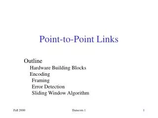
FRAMING The data link layer needs to pack bits into frames, so that each frame is distinguishable from another. Our postal system practices a type of framing. The simple act of inserting a letter into an envelope separates one piece of information from another; the envelope serves as the delimiter. Topics discussed in this section: Fixed-Size FramingVariable-Size Framing
Note Byte stuffing is the process of adding 1 extra byte whenever there is a flag or escape character in the text.
Note Bit stuffing is the process of adding one extra 0 if 011111 is encountered in data, so that the receiver does not mistake the pattern 0111110 for a flag.
FLOW AND ERROR CONTROL The most important responsibilities of the data link layer are flow control and error control. Collectively, these functions are known as data link control. Topics discussed in this section: Flow ControlError Control
Note Flow control refers to a set of procedures used to restrict the amount of data that the sender can send before waiting for acknowledgment.
Note Error control in the data link layer is based on automatic repeat request, which is the retransmission of data.
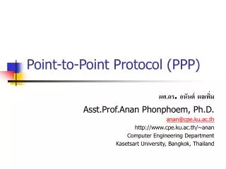
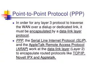
The PPP protocol is a data link protocol for transmission on a serial link Use of PPP today: Dial-in or DSL access to Internet Routers connected by point-to-point links Main purpose of PPP isencapsulation of IP datagrams PPP was proposed in 1992; a predecessor of PPP was the Serial Link IP (SLIP) protocol PPP - Point-to-Point Protocol
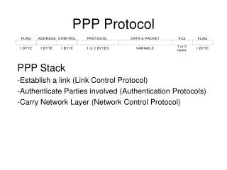
The frame format of PPP is similar to HDLC and the 802.2 LLC frame format: PPP - IP encapsulation
Other than a framing method PPP provides: The link control protocol (LCP) which is responsible for establishing, configuring, and negotiating a data-link connection LCP is specified in RFC 1331. For each network layer protocol supported by PPP, there is one network control protocol (NCP) The NCP for IP is specified in RFC 1332 PPP
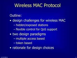
In any broadcast network, the stations must ensure that only one station transmits at a time on the shared communication channel The protocol that determines who can transmit on a broadcast channel are called Medium Access Control (MAC) protocol The MAC protocol are implemented in the MAC sublayer which is the lower sublayer of the data link layer The higher portion of the data link layer is often called Logical Link Control (LLC) MAC and LLC