Download
1 / 23
240 likes | 400 Vues
Folding DNA to Create Nanoscale Shapes and Patterns Paul W. K. Rothemund Nature, V440, 297-302, 2006. Sunmin Ahn Journal Club Presentation October 23, 2006. Outline. Introduction Review of DNA structure Designing DNA origami Folding with viral genome Patterning Conclusion.

E N D
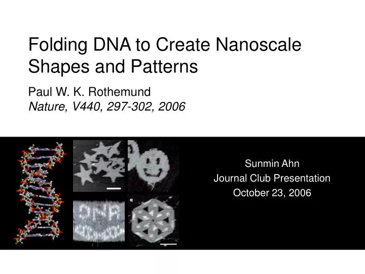
Folding DNA to Create Nanoscale Shapes and PatternsPaul W. K. RothemundNature, V440, 297-302, 2006 Sunmin Ahn Journal Club Presentation October 23, 2006
Outline • Introduction • Review of DNA structure • Designing DNA origami • Folding with viral genome • Patterning • Conclusion
Introduction • Parallel synthesis of nanostructures • Building DNA patterns and shapes with a long ssDNA and a bunch of staple strands • One pot self assembly
Designing Pattern - Manual design 1. Generation of block diagram 2. Generation of a folding path - raster fill pattern must be hand designed
Designing Pattern - Computer aided 3. Generation of a first pass design - raster fill pattern must be hand designed - no bases left unpaired - single phosphate from each backbone occurs in the gap - small angle bending does not affect the width of DNA origami
Designing Pattern - Computer aided 4. Refinement of the helical domain length - to minimize strain in design - twist of scaffold calculated and scaffold x-over strains are balanced by a single bp change - periodic x-overs of staples are arranged with glide symmetry minor groove faces alternating directions in alternating columns
Designing Pattern - Computer aided 5. Breaking and merging of strands - pairs of adjacent staples are merged to yield fewer, longer staples - merge patterns are not unique - staggered merge strengthens seam
Designing Pattern - Computer aided 5. Breaking and merging of strands - rectilinear merge
Folding viral genome • Circular genomic DNA from virus M13mp18 chosen as a scaffold • Naturally ssDNA 7249-nt long • For linear scaffold 73-nt region containing 20-bp stem hairpin was cut with BsrBI restriction enzyme • resulting 7167nt long linear strand • 100X excess of staples and short (<25nt) remainder strands mixed with scaffold and annealed 95ºC to 20ºC in a PCR machine (< 2 hours) • Samples deposited on mica and imaged with AFM in tapping mode
Folding viral genome • Square • linear scaffold • 13% well formed • 25% rectangular fragments • 25% hourglass fragments • Rectangle • tests “bridged” seam • circular scaffold • 90% well formed 1μm scale bars
Folding viral genome • Star • demonstrates certain arbitrary shape • linear and circular scaffold • 11% and 63% well formed • higher % of well formed shapes with circular scaffold may be due to higher purity of the scaffold strand Circular scaffold Linear scaffold 100nm scale bars • Smiley • circular scaffold • need not be topological disc • 90% well formed • narrow structures are difficult to form provides “weak spot” 100nm scale bar
Folding viral genome • Triangle from 3 rectangles • single covalent bond holding the scaffold together • less than 1% well formed • stacking 100nm scale bar • Triangle built from 3 trapezoids • circular scaffold • 88% well formed with bridging staples • 55% well formed without bridging staples 100nm scale bar
Stacking Interaction between blunt end helices cause stacking A B • Staple strands on the edge may be removed (B) • Addition of 4T hairpin loops (F) • Addition of 4T tails on staples that has ends on the edge of the shape (D) Stacked rectangles Staple strand on the edge removed F C D Normal amount of aggregation (Smileys) Addition of 4T tails 1μm scale bars
Defects and Damages 100nm scale bars
Stoichiometry • In most experiments 100~300 fold excess over scaffold was used • 10 fold excess is safe, but not a fundamental requirement • 2-fold excess may be used 1μm scale bars
Patterning Binary patterning “1” – 3nm above mica surface “0” – 1.5nm above mica surface 1μm scale bars
Patterning • Infinite periodic structures are made using extended staples • Stoichiometry becomes very important • ~30 Megadalton structure (individual origami ~4megadalton) 100nm scale bars
Difficulties • Blunt end stacking • Down hairpin loops • But mostly AFM imaging!!!
What about 2º Structures? • Lowest E folds calculated Strong structure Weak structure • Average -965+-37kcal/mole • Random 6000 base sequence generated with same base composition as M13mp18 • - Similar 2º structure • - Average free E -867 +- 13kcal/mole
How does it work? • Strand invasion • Excess of staples • Cooperative effects • Designs that doesn’t allow staples to bind to each other
Conclusion • Quantitative and statistical analysis • Better imaging technique should be implemented • DNA nonostructure patterning may be used as templates for programmed molecular arrays • Protein arrays • nanowires