Download
1 / 15
150 likes | 254 Vues
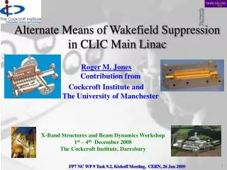
Alternate Means of Wakefield Suppression in CLIC Main Linac. Roger M. Jones, Vasim Khan, Alessandro D’Elia Cockcroft Institute, UK and The University of Manchester, UK. Overview of Wakefield Suppression.

E N D
Alternate Means of Wakefield Suppression in CLIC Main Linac Roger M. Jones, Vasim Khan, Alessandro D’Elia Cockcroft Institute, UK andThe University of Manchester, UK
Overview of Wakefield Suppression • Alternate method entails heavy detuning and moderate damping of a series of interleaved structures (known as CLIC_DDS). This is a similar technique to that experimentally verified and successful employed for the NLC/GLC program. • Integration of Task 9.2 within NC WP 9 -anticipate test of CLIC_DDS on modules • Potential benefits include, reduced pulse temperature heating, ability to optimally locate loads, built-in beam and structure diagnostic (provides cell to cell alignment) via HOM radiation. Provides a fall-back solution too! • Initial studies encouraging. However, the challenge remains to achieve adequate damping at 0.5 ns intra-bunch spacing
Alternate Design CLIC Accelerating Structure Acceleration cells Beam tube Manifold HOM coupler High power rf coupler • DDS (NLC/GLC design) illustrates the essential features of the conceptual design • Each of the cells is tapered –iris reduces with an Erf-like distribution • HOM manifold running alongside main structure remove dipole radiation and damp at remote location (4 in total) • Each of the HOM manifolds can be instrumented to allow: 1) Beam Position Monitoring2) Cell alignments to be inferred Damped and Detuned Structure (DDS)
FP7 CLIC_DDS -Staff • Roger M. Jones (Univ. of Manchester faculty) • Alessandro D’Elia (Dec 2008, Univ. of Manchester PDRA based at CERN) • Vasim Khan (Ph.D. student, Sept 2007) • Collaborators: W. Wuensch, A. Grudiev (CERN) A. D’Elia, CI/Univ. of Manchester PDRA based at CERN (former CERN Fellow). V. Khan, CI/Univ. of Manchester Ph.D. student pictured at EPAC 08
Integration of Task 9.2 within NC WP 9 Abstract of the planned activity This work package will explore HOM damping in single multi-cell cavities and in groups of thereof. The features of both the long-range and short-range wake-fields will beexplored. The consequences of the short-range wake-field on cavity alignment will be delineated. For the long-range wake-fields, trapped modes in particular will be focused upon. Global scattering matrix analysis will be employed in addition to current electromagnetic codes. The frequency sensitivity of the modes will be explored by exploiting a circuit analysis of the electromagnetic field and this will enable the sensitivity of the wake-field to fabrication errors to be evaluated over the complete collider. At the University of Manchester and the Cockcroft Institute we are actively involved in simulating higher order modes of accelerating cavities and experimentally determining the structure of these modes with a purpose built stretched wire measurement set-up. We are actively involved in using intensive computer codes coupled with cascading of individual sections in order to rapidly compute the modal structure.
Integration of Task 9.2 within NC WP 9 • List of Goals and Milestones • Goal 1. Develop a circuit model and a generalized scattering matrix technique to obtain accurate calculations on the global electromagnetic field from small segments thereof. This is a study of mode excitation. • Milestones • 1.1 Sep 09: Write report on circuit model and globalised scattering matrix technique. This will include an analysis of the partitioning of dipole modes in CLIC structures • 1.2 Apr 110: Produce a report for the design of damping and detuning a CLIC module • Goal 2. Make an accurate simulation of the wake-fields and HOMS. This is expected to be broadly verified with initial experiments on CTF3 and more precisely verified with an experiment at the SLAC FACET facility and stretched wire measurements. • Milestones • 2.1 Apr 10: Experiments on the measurement of HOMs on CTF3. This will enable the predicted features of HOM damping to be verified although only the broad characteristics of the modes are expected to be measurable. • 2.2 Aug 10: Perform additional measurements on the wake-field at the SLAC FACET facility. This will facilitate a detailed comparison between the predicted decrement in the wake envelope and experimentally determined values. ASSET typically is accurate to ~ 0.01 V/pC/mm/m.
Integration of Task 9.2 within NC WP 9 • 2.3 Sept 10: Write up a report on the experimental measurement of modes. • 2.4 April 11: Conduct wire measurement on CLIC cavities to verify the distribution of frequencies and kick factors • Goal 3. Undertake beam dynamics simulations with Placet. These simulations will take into account both the long-range and short-range wake-fields. Simulations will be performed both with the baseline design and with relaxed fabrication tolerances. In addition to the standard wake-field the influence of x-y coupling of wake-fields from possible cavity distorsions will also be investigated. • Milestones • 3.1 April 11: Initial result on baseline beam dynamics simulations • 3.2 June 11: Results on beam dynamics simulations with relaxed tolerances and initial simulations on transverse mode coupling • 3.3 August 11: Report on beam dynamics simulations including long and short range wakefields. • 3.3 Sept 11: Report on beam dynamics simulations including transverse mode coupling • Major goal: Design and measure wakefield suppression in module
Wealth of Experience on Detuned Structure and Manifold Wakefield Suppression • More than one and half decades of experience in this area
Wealth of Experience on Detuned Structure and Manifold Wakefield Suppression DDS3 DDS1 H60VG4SL17A/B RDDS1 1. Influence of fabrication errors on wake function suppression in NC X-band accelerating structures for linear colliders, R.M. Jones et al. 2009 New J. Phys. 11 033013 (13pp). 2. Wakefield damping in a pair of X-band accelerators for linear colliders.R.M. Jones et al., Phys.Rev.ST Accel.Beams 9:102001,2006.
Circuit Model of CLIC_DDS Coupled 3rd mode Uncoupled 2nd mode Uncoupled 1st mode Avoided crossing Light line Uncoupled manifold mode Three cells in the chain are illustrated. TM modes couple to the beam. Both TM and TE modes are excited (hybrid dipole mode). Coupling to the manifold takes place via slot-coupled TE modes. Manifold is modelled as a transmission line Cell 1 E-Field and Dispersion Curves for CLIC_DDS Refs: 1. Wakefield damping in a pair of X-band accelerators for linear colliders.R.M. Jones , et al., Phys.Rev.ST Accel.Beams 9:102001,2006. 2. Influence of fabrication errors on wake function suppression in NC X-band accelerating structures for linear colliders, R.M. Jones et al 2009 New J. Phys. 11 033013 (13pp).
Wake-field Suppression in CLIC_DDS Main Linac -Initial design • Circuit model provides rapid determination of optimal wakefield suppression results in a bandwidth of 3.6 (3.36 GHz) and f/ fc =20%. • Leftmost indicates the modal distribution and rightmost the coupled and uncoupled wakefield • Four-fold interleaving of successive structures results in excellent wake-field suppression at the location of each bunch • Meets CLIC beam dynamics requirements! • However, breakdown considerations require a redesign with additional constraints imposed Uncoupled dn/df Kdn/df Coupled Envelope of Wakefield for Single 25-Cell Structure (Q ~ ∞) Kick Factor Weighted Density Function Wakefield for 8-Fold Interleaved Structure (Q ~ ∞) Envelope of Wakefield for 4-Fold Interleaved Structure (Finite Q )
2. Parameters of WDS-120 protos @14.4Wu Alexej Grudiev (CERN)
Wake-field Suppression in CLIC Main Linac -Redesign dn/df Kdn/df Q ~ 300 Non-interleaved Interleaved – (uncoupled-undamped) Interleaved • Interleaving improves sampling of wake function and enhances falloff • Bandwidth restricts the rate of decay of the wake function • Additional work entails: 1. relaxing the bandwidth restriction, enabling better sampling (more cells/structure) 2. reoptimisation of Kdn/df distribution 3. non-linear positioning of interleaved frequencies • Initial redesign tied to present (CLIC_G)) cell parameters –cell 1 and 24 • Frequencies and kick factor weighted density function Kdn/df from 4-fold interleaving of structures shown • This restricts the bandwidth /2 ~1 GHz ~ 3 Investigation of an alternate means of wakefield suppression in the main linacs of CLIC, V. Khan and R.M. Jones, Proceedings of PAC09.
Overall Goals • Provide proof-of-principle of manifold damped and detuned design and structure test at CTF3 • Overall properties of wakefield suppression to be tested in modules at CTF3 (SLAC FACET?) • Provide typical tolerances/alignments for practical multi-structure operation (from PLACET beam dynamics simulations) –CLIC! • N.b. this structure has the potential for a significantly smaller pulse temperature rise than the present baseline design for CLIC
Summary • Analytical truncated Gaussian is a useful design tool to predict wakefield suppression. • Initial design provides a well-damped wakefield. • Including the constraints imposed by breakdown forces a consideration of zero-point crossing. • Beam dynamics study including systematic and random errors in progress –will provide detailed answer. • Manifold damping provides useful characteristics of built-in BPM together with a direct indication of internal alignments