Download
1 / 16
160 likes | 318 Vues
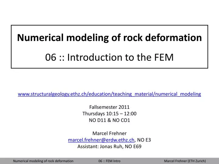
Numerical modeling of rock deformation 06 :: Introduction to the FEM. www.structuralgeology.ethz.ch/education/teaching_material/numerical_modeling Fallsemester 2011 Thursdays 10:15 – 12:00 NO D11 & NO CO1 Marcel Frehner marcel.frehner@erdw.ethz.ch , NO E3 Assistant: Jonas Ruh, NO E69.

E N D
Numerical modeling of rock deformation06 :: Introduction to the FEM www.structuralgeology.ethz.ch/education/teaching_material/numerical_modeling Fallsemester 2011 Thursdays 10:15 – 12:00 NO D11 & NO CO1 Marcel Frehner marcel.frehner@erdw.ethz.ch, NO E3 Assistant: Jonas Ruh, NO E69
Goals of today • Derive the weak form of the governing equation • Understand the fundamental principle ofthe finite element approximation • Apply the Galerkin method • Understand how to put together the global stiffness matrix
The big picture – Physical models • Mechanical framework • Continuum mechanics • Quantum mechanics • Relativity theory • Molecular dynamics • Solution technique • Analytical solution • Linear stability analysis • Fourier transform • Green’s function • Numerical solution • Finite difference method • Finite element method • Spectral methods • Boundary element method • Discrete element method • Constitutive • Equations • (Rheology, • Evolution • equation) • Elastic • Viscous • Plastic • Diffusion • Governing equations • Energy balance • Conservation laws • Differential equations • Integral equations • System of (linear) equations • Solution is valid • for the applied • Boundary conditions • Rheology • Mechanical framework • etc… • Closed system of equations • Boundary and initial conditions • Heat equation • Navier-Stokes equation • Wave equation Dimensional analysis
Numerical methods There are different numerical methods, e.g.: • Finite difference method (FDM) • Finite element method (FEM) • Finite volume method (FVM) • Spectral method • Discrete element method (DEM) • Boundary element method (BEM) Advantages of the FEM • Rectangular grid or unstructured mesh Easy to fit complex geometries • Deforming mesh (interface tracking) • Free surface / topography • Very flexible • Well suited for • All geodynamical problems involving (large) deformation • All problems with complex geometries
u B x 0 L The model equation We consider the equation This equation is a second order, inhomogeneous, constant-coefficientlinearordinary differential equation. It may represent: • 1D Steady state heat conduction withradiogenic heat production(A=a: thermal diffusivity; B=q:heat production; u=T: temperature) • Viscous fluid flow betweenparallel plates (A=h: viscosity;B=p: pressure drop; u=v: velocity) • Deflection of a stretched wireunder lateral load(A=s: tension; B=f: lateral load;u=w: deflection) Case a) Case c)
Analytical solution • First integration: • Second integration: • Find the two integrationconstants by applyingboundary conditions: • Solution:
FEM: The weak form – 1 • Assumptions: Continuous anddifferentiable function u(x) inthe 1D space x=[0...L] • Multiplication with test functions: • Spatial integration: • Integration by parts: The product ruleof differentiation
FEM: The weak form – 2 • The first terms are the so-called boundary terms, i.e., the spatial derivative of function u(x) has to be evaluated at the boundaries. They will anyway be defined by the boundary conditions (see later). Therefore, we do not need to take them into consideration. • This is the weak form of our original equation, because it has weaker constraints on the differentiability of the solution (i.e., only first derivative compared to second derivative). Original equation
The finite element approximation – 1 We approximate function u(x) within the finite element [xi…xi+1] as a sum of known functions, the so-called shape functions, multiplied with the values of u(x) at the nodal points, u(xi) and u(xi+1). Linear 1D Shape functions • Requirements for the shape functions: • Equal 1 at one nodal point; equal 0 at all other nodal points. • Sum of all shape functions has to be 1 in the whole finite element. • Shape functions can approximate functions of the same or lower order.
The FEM where the shape functions are identical to the test (weight) functions is called Galerkin method after Boris Galerkin. The finite element approximation – 2 Weak form: FEM approximation:
The finite element approximation – 3 K: Stiffness matrix F: Force vector Solve derivatives and integrals analytically: Linear 1D Shape functions
The finite element approximation – 4 Local system for element 1 Local system for element 2 Global system = Sum of all elements Example: 2 finite elements
Boundary conditions Global system withoutboundary conditions Implementing boundary conditions u1=c1 and u3=c2 Example: 2 finite elements
Programming finite elements – 1 Example: 9 finite elements • Which nodes belongto which element? • Introduce an indexing matrix (EL_N): • Matrix EL_N assigns to each local element the corresponding global nodes. Local element
Programming the finite element – 2 Example: 9 finite elements Local system for finite element 5 4 5 4 Check in EL_N where to find element 5 in the global system 5
Programming the finite elements – 3 The global stiffness matrix is the sum of all local stiffness matrices. In our code we will first setup a global stiffness matrix, Kglobal, full of zeros. Then we will • loop through the finite elements • Identify where the local element is positioned within the global matrix • add the local stiffness matrix to the global one at the correct position Exactly the same is done for the global right-hand-side vector Fglobal