Download
1 / 31
310 likes | 379 Vues
Antennas. 1. Source: Adapted with permission from M. Chryssomallis, “Smart Antennas,” IEEE Antennas and Propagation Magazine, vol. 42, no. 3, June 2000, pp. 129–136. Figure 13.1 An antenna as a matching device between the guiding structure and the surrounding medium.

E N D
Antennas 1
Source: Adapted with permission from M. Chryssomallis, “Smart Antennas,” IEEE Antennas and Propagation Magazine, vol. 42, no. 3, June 2000, pp. 129–136. Elements of Electromagnetics Fourth Edition Sadiku
Figure 13.1 An antenna as a matching device between the guiding structure and the surrounding medium. Elements of Electromagnetics Fourth Edition Sadiku
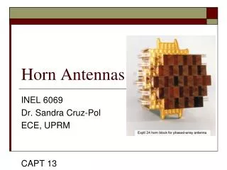
Figure 13.2 Typical antennas. Elements of Electromagnetics Fourth Edition Sadiku
Figure 13.3 A Hertzian dipole carrying current I =Io cos wt. Elements of Electromagnetics Fourth Edition Sadiku
Figure 13.4 (a) A half-wave dipole. (b) Geometry for calculating the fields. Elements of Electromagnetics Fourth Edition Sadiku
Figure 13.5 The monopole antenna. Elements of Electromagnetics Fourth Edition Sadiku
Figure 13.6 The small loop antenna. Elements of Electromagnetics Fourth Edition Sadiku
Figure 13.7 Field patterns of the Hertzian dipole: (a) normalized E-plane or vertical pattern (f= constant = 0), (b) normalized H-plane or horizontal pattern (q=p/2), (c) three-dimensional pattern. Elements of Electromagnetics Fourth Edition Sadiku
Figure 13.8 Power patterns of the Hertzian dipole: (a) f= constant = 0, (b) q= constant =p/2. Elements of Electromagnetics Fourth Edition Sadiku
Figure 13.9 Relating Pin, Pℓ, and Prad. Elements of Electromagnetics Fourth Edition Sadiku
Figure 13.10 A two-element array. Elements of Electromagnetics Fourth Edition Sadiku
Figure 13.11 An N-element uniform linear array. Elements of Electromagnetics Fourth Edition Sadiku
Figure 13.12 Array factors for uniform linear arrays. Elements of Electromagnetics Fourth Edition Sadiku
Figure 13.13 For part (a) of Example 13.6: field patterns in the plane containing the axes of the elements. Elements of Electromagnetics Fourth Edition Sadiku
Figure 13.14 For part (b) of Example 13.6; field patterns in the plane containing the axes of the elements. Elements of Electromagnetics Fourth Edition Sadiku
Figure 13.15 For Practice Exercise 13.6. Elements of Electromagnetics Fourth Edition Sadiku
Figure 13.16 For Example 13.7: (a) a three-element array with current ratios 1: 2 : 1; (b) and (c) equivalent two-element arrays. Elements of Electromagnetics Fourth Edition Sadiku
Figure 13.17 For Example 13.7; obtaining the resultant group pattern of the three-element array of Figure 13.16(a). Elements of Electromagnetics Fourth Edition Sadiku
Figure 13.18 For Example 13.7 and Practice Exercise 13.7: four-element array with current ratios 1: 3 : 3: 1. Elements of Electromagnetics Fourth Edition Sadiku
Figure 13.19 For part (a) of Practice Exercise 13.7. Elements of Electromagnetics Fourth Edition Sadiku
Figure 13.20 Thévenin equivalent of a receiving antenna. Elements of Electromagnetics Fourth Edition Sadiku
Figure 13.21 Transmitting and receiving antennas in free space. Elements of Electromagnetics Fourth Edition Sadiku
Figure 13.22 (a) Typical radar system. (b) Simplification of the system in (a) for calculating the target cross sections. Elements of Electromagnetics Fourth Edition Sadiku
Figure 13.23 Typical examples of intersystem EMI problems. Source: J. I. N. Violette et al., Electromagnetic Compatibility Handbook. New York: Van Nostrand Reinhold, 1987, p. 4. Elements of Electromagnetics Fourth Edition Sadiku
Figure 13.24 Differences between conducted and radiated emissions. Elements of Electromagnetics Fourth Edition Sadiku
Figure 13.25 Short dipole antenna with triangular current distribution; for Problem 13.5. Elements of Electromagnetics Fourth Edition Sadiku
Figure 13.26 Two-element array of Problem 13.28. Elements of Electromagnetics Fourth Edition Sadiku
Figure 13.27 For Problem 13.34. Elements of Electromagnetics Fourth Edition Sadiku
Figure 13.28 For Problem 13.46. Elements of Electromagnetics Fourth Edition Sadiku
Figure 13.29 For Problem 13.48. Elements of Electromagnetics Fourth Edition Sadiku