1 / 62

Interference Sphere: Collision Checking for Assembly in Horizontal Plane

This simulation showcases the creation of an interference sphere as a critical space for collision checking during the assembly of product Hi6, Hi3, Hi2, Hi4, Hi5. The disassembly sequence, positioning of parts, and final assembly simulation are demonstrated. Additionally, the generation of a new plan variant and changing the initial orientation of the product are explored.

Télécharger la présentation

Interference Sphere: Collision Checking for Assembly in Horizontal Plane

An Image/Link below is provided (as is) to download presentation Download Policy: Content on the Website is provided to you AS IS for your information and personal use and may not be sold / licensed / shared on other websites without getting consent from its author. Content is provided to you AS IS for your information and personal use only. Download presentation by click this link. While downloading, if for some reason you are not able to download a presentation, the publisher may have deleted the file from their server. During download, if you can't get a presentation, the file might be deleted by the publisher.

E N D

Presentation Transcript


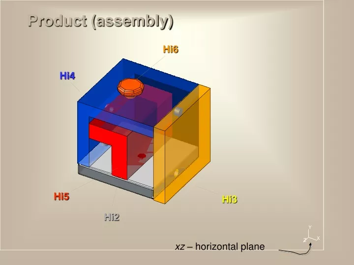
  1. Hi6 Hi4 Hi5 Hi3 Hi2 Product (assembly) xz – horizontal plane

  2. CREATION OF THE INTEREFERENCE SPHERE – critical space for collision checking among parts. INITIAL DISASSEMBLY SEQUENCE: Hi6, Hi3, Hi2, Hi4, Hi5.

  3. Finding out disassembly path for the partHi6.

  4. PartHi6 disassembled.

  5. PartHi3 disassembled.

  6. PartHi2 disassembled.

  7. PartHi4 disassembled.

  8. The positions of the parts immediately after disassembly – the main partHi5is left in its initial position.

  9. POSITIONING OF THE PARTS IN FINAL POSITIONS AFTER DISASSEMBLY – POSITIONS BEFORE ASSEMBLY...

  10. PartHi3positioned.

  11. PartHi4positioned.

  12. The main partHi5positioned.

  13. PartHi2positioned.

  14. PartHi6positioned.

  15. ASSEMBLY SIMULATION FOLLOWS...

  16. Assemble (main) partHi5... X = -8.146965 Y = 0 Z = 617.1062

  17. AssemblepartHi4... 271.5267 0 0 276.4636 0 0

  18. AssemblepartHi4... 271.5267 0 0 276.4636 0 0

  19. Rotate assembly...

  20. Move partHi2... -313.5974 0 -534.4296

  21. Project partHi2...

  22. Assemblepart Hi2... -1.05846E-13 -276.4636 0

  23. Rotate assembly...

  24. Assemblepart Hi3... -271.5267 0 0 -276.4636 0 0

  25. Assemblepart Hi3... -271.5267 0 0 -276.4636 0 0

  26. Move partHi6... 293.8073 0 -534.4296

  27. Assemblepart Hi6... 1.05846E-13 -276.4636 0

  28. Move product (assembly)... 8.146965 0 -617.1062

  29. Assembly finished!

  30. CHANGING OF THE PRODUCT`S INITIAL ORIENTATION – avoiding assembly of the part Hi2from beneath. GENERATION OF THE NEW PLAN VARIANT

  31. PRODUCT`S NEW ORIENTATION

  32. CREATION OF THE INTERFERENCE SPHERE INITIAL DISASSEMBLY SEQUENCE: Hi6, Hi3, Hi2, Hi5, Hi4.

  33. PartHi6 disassembled.

  34. PartHi3 disassembled.

  35. PartHi2 disassembled.

  36. PartHi5 disassembled.

  37. Positions of the parts immediately after disassembly – the main part Hi4is left in its initial position.

  38. POSITIONING OF THE PARTS IN FINAL POSITIONS AFTER DISASSEMBLY – POSITIONS BEFORE ASSEMBLY...

  39. PartHi6 positioned...

  40. PartHi3 positioned...

  41. PartHi2 positioned...

  42. PartHi5 positioned...

  43. The correction of the position of the partHi3...

  44. The main partHi4 positioned...

More Related