Download
1 / 29
350 likes | 521 Vues
WASTE HEAT BOILER. GROUP MEMBERS. 06-CHEM-06 06-CHEM-46 06-CHEM-48. INTRODUCTION. Waste heat boiler:

E N D
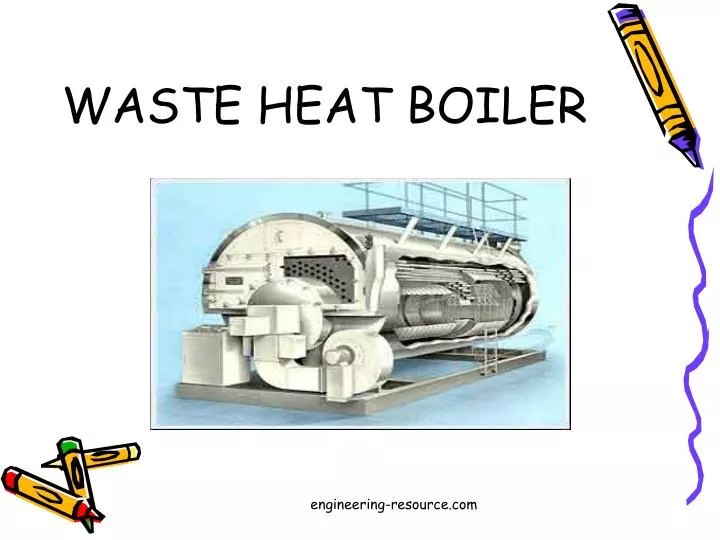
WASTE HEAT BOILER engineering-resource.com
GROUP MEMBERS 06-CHEM-06 06-CHEM-46 06-CHEM-48 engineering-resource.com
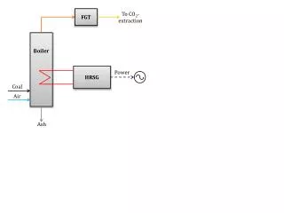
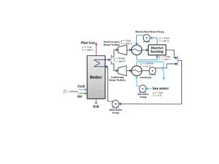
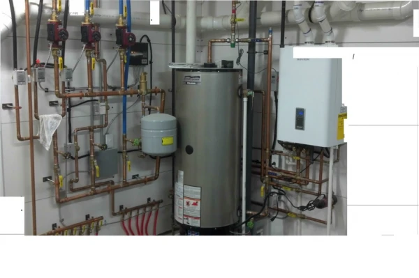
INTRODUCTION Waste heat boiler: A heat-retrieval unit using hot by-product gas or oil from chemical processes; used to produce steam in a boiler-type system is known as waste heat boiler. It is also known as gas-tube boiler. engineering-resource.com
Waste heat boilers may be horizontal or vertical shell boilers or water tube boilers. They would be designed to suit individual applications ranging through gases from furnaces, incinerators, gas turbines and diesel exhausts. The prime requirement is that the waste gases must contain sufficient usable heat to produce steam or hot water at the condition required. Waste-heat boilers may be designed for either radiant or convective heat sources. engineering-resource.com
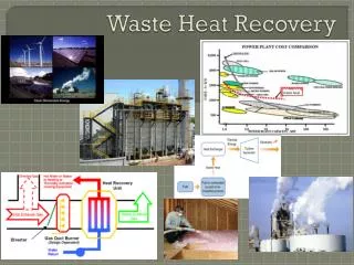
Heat Recovery In Process Plants • Competitive market conditions on the most products make it essential to reduce processing cost • The cost of fuels keeps rising • Limited fuel availability is already causing plant interruptions • There is restriction in using some of the lower-cost fuels because of environmental pollution engineering-resource.com
Increasing emphasis is being placed on the minimizing thermal pollution • Increasing amounts of elevated-temperature flue gas streams are becoming available from gas turbines, incinerators, etc. engineering-resource.com
Applications • For process heating. (Steam usually generated at 125-650 psig) • For power generation. (usually generated at 650-1500 psig and will require superheating) • For use as a diluents or stripping medium in a process. This is a low-volume use. engineering-resource.com
Problem Determine the size of a fire tube waste heat boiler required to cool 100,000 lb/h of flue gases from 1500oF to 500oF. Gas analysis is (vol%) CO2=12, H2O=12, N2 =70, and O2 =6; gas pressure is 5 in.WC. Steam pressure is 150 psig, and feed water enters at 220oF. Tubes used are in 2 in. OD*1.77 in. ID engineering-resource.com
Data Given • Fouling factors are Gas side (ft) = 0.002 ft2 h oF/Btu Steam side (ff) = 0.001 ft2 h oF/Btu • Tube metal thermal conductivity, km =25 Btu/ft2 h oF • Steam side boiling heat transfer coefficient, ho = 2000 Btu/ft2oF • Heat losses = 2%. engineering-resource.com
At the average gas temperature of 1000oF, the gas properties can be shown to be • Cp =0.287 Btu/lb oF • µ=0.084 lb/ft h • k =0.0322 Btu/ft h oF. engineering-resource.com
Density Calculations MWmix = ∑ (MWi Xi) =(0.12)(44)+(0.12)(18)+(0.70)(28)+(0.06)(32) = 28.96 lb/lbmole Density at standard temperature, ρ = 28.96/359 = 0.0806 lb/ft3 engineering-resource.com
Density at mean temperature, ρm =ρ (T/T2) = (0.0806) (492)/(1492) = 0.027 lb/ft3 engineering-resource.com
Heat Duty Boiler duty Q = Wg CP(T1 –T2)(1-L\100) = 100,000 X 0.98 X 0.287X (1500 -500) = 28.13 X 10⁶ Btu/hr engineering-resource.com
From steam tables Enthalpies of saturated steam H1= 1195.5 Btu/lb Enthalpies of saturated water H2 = 338 Btu/lb Latent heat of steam, λ = 857.8 Btu/lb engineering-resource.com
Water Flow Rate ∆H = H2 – H1 = 1015 Btu/lb m’ = Q \ (∆H ) = (28.13 X 10⁶)/(1015) = 27,710 lb/hr engineering-resource.com
LMTD weighted Log-mean temperature difference ∆T = (1500 – 366)-(500 -366) ln(1500 -366)/(500 – 366) = 468 oF engineering-resource.com
Flow per tube Typically w ranges from 100 to 200 lb/hr for a 2 in tube. Let us start with 600 tubes, hence w = 100,000/600 = 167 lb/hr engineering-resource.com
Inside Film Coefficient hi = 2.44 X w0.8 XC/di1.8 C = (CP/µ)0.4X k0.6 = (0.287/0.084)0.4 X (0.0322)0.6 = 0.208 hi = (2.44 X 0.208 X (167)0.8)/(1.77)1.8 =10.9 Btu/ft2 hr oF engineering-resource.com
Overall Heat Transfer Coefficient 1/U = (do/di)/ hi + ffo + ffi (do/di) + do ln(do/di)/24Km +1/ho = 0.10+0.001+0.00226+0.00041+0.0005 = 0.10417 Hence, Uo= 9.6 Btu/ft2 hr oF engineering-resource.com
If U is computed on the basis of tube inner surface area, then Ui is given by the Q= Ui Ai (LMTD) (1) If U is computed on the basis of tube outer surface area, then Uo is given by the Q= Uo Ao (LMTD) (2) engineering-resource.com
We get, Ui Ai = Uo Ao Ui = 9.6 X 2/1.77 = 10.85 Btu/ft2 hr oF engineering-resource.com
Putting back in eq.2 Ao = (28.13X10⁶)/(468 X 9.6) = 6261 ft Ao= л nt d L 6261 = 3.14X2X600(L/12) L = 19.93 ft so required length L of the tubes=19.93 ft. Use 20 ft. engineering-resource.com
Area Calculation So, the required total area is Ao = 3.14 X 2 X 600 X (20/12) = 6280 ft2 Ai = 5558 ft2 engineering-resource.com
Thickness Of Shell Ts = P(D+2C)/ [(2fJ-P)+C] Where, P = design pressure D = inner diameter of shell C = corrosion allowance f = permissible stress factor J = welded joint factor engineering-resource.com
From literature we know that, for Carbon steel C= 1/8 of an inch f= 13400psi J=0.75 - 0.95 We get, Ts = 0.6584 in engineering-resource.com
Outer diameter of tube bundle = 1.32 X do X (nt)½ = 64.66 in Providing allowances for welding, = 64.66 + 6 = 70.66 in Shell diameter, DS = 70.66 X 1.20 = 84.8 in engineering-resource.com
PRESSURE DROP CALCULATIONS Tube side pressure drop: V = 0.05 W/diρg V = 19520 ft/ hr Re = ρgdiV/µ = 890.12 f = 0.02 (from graph) engineering-resource.com
∆Pg = 93 X 10-6 X w2f Le /ρgdi5 Where Le = equivalent length = L+5di (tube inlet and exit losses) engineering-resource.com
∆Pg = 93 X 10-6X 1672X 0.02 X (20+5 X 1.77) 0.0267 X (1.77)5 = 3.23 in. WC engineering-resource.com