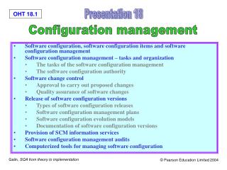
Download
1 / 17
170 likes | 416 Vues
Art for Chapter 10, Software Configuration Management. Figure 10-1. Configuration management concepts (UML class diagram). A320:CM Aggregate. Fly-by-wire SW:CI. Landing Gear:CM Aggregate. Fuselage:CI. Wing:CI. Tire:CI.

E N D
Figure 10-1. Configuration management concepts (UML class diagram).
A320:CM Aggregate Fly-by-wire SW:CI Landing Gear:CM Aggregate Fuselage:CI Wing:CI Tire:CI Figure 10-2. An example of CM aggregates and configuration items (UML object diagram).
First release A320:Baseline revised by derived from derived from A320-200:Revision Improved version including winglets A319:Baseline A321:Baseline 124 seat variant 185 seat variant Figure 10-3. Examples of baselines, revisions, and variants (UML object diagram). The A319, A320, and the A321 are all based on the same design. They vary mostly by the length of their fuselage.
Alpha test release MUE.0.0.1:Release MUE.1.0.0:Release First major release Second minor release MUE.1.2.1:Release with bug fixes Second major MUE.2.0.3:Release release with three series of bug fixes Three-digit version identification scheme <version> ::= <configuration item name>.<major>.<minor>.<revision> <major> ::= <nonnegative integer> <minor> ::= <nonnegative integer> <revision> ::= <nonnegative integer> Figure 10-4. Three digit version identification scheme (BNF and UML object diagram).
MUE.1.1:Release MUE.1.2:Release MUE.1.3:Release 1.2.1.1:Release 1.2.1.2:Release MUE.2.0:Release CVS version identification scheme <version> ::= <configuration item name>.<version identifier> <version identifier> ::= <branch>.<revision> <branch> ::= <version identifier>.<branch number> | <branch number> <branch number> ::= <nonnegative integer> <revision> ::= <nonnegative integer> Main trunk revised by derived from Branch 1.2.1 revised by merged with revised by released as Figure 10-5. CVS version identification scheme (UML object diagram). Branches are identified with the version they were derived from followed by a unique number.
Figure 10-6. Change set representation of the MUE release history (UML object diagram). dashedLineFix:ChangeSet and emptyClassFix:ChangeSet can be applied to the MUE.1.0:Release in arbitrary order because they do not overlap.
The :DealerPC is the machine used by a dealer to order parts. The :DealerPC has often a higher bandwidth link to the server. The :EClient allows an expert user to find parts by part identifier, vehicle make and year, and order history. The :EClient is for high-volume clients, e.g., car repair shops. The :Server enables client to retrieve lists of parts by criteria and part entries, to order parts, and to track client activity. The :ServerHost hosts the parts catalog server. The :HomePC is the machine used by a car owner to order parts. The :HomePC is connected to the server via a modem. The :NClient enables a novice user to find parts by description and, in subsequent releases, by clicking on a vehicle map. The :NClient is for the occasional client, e.g., a car hobbyist. Figure 10-7. MyCarParts subsystem decomposition and hardware allocation (UML deployment diagram).
Figure 10-8. Configuration items and CM aggregates for myCarParts (UML object diagram).
Figure 10-9. Snapshot of the workspaces used by myCarParts developers (UML object diagram). The Novice Workspace, the Tech Writer Workspace, and the Server Workspace contain promotions related to the navigation map functionality. The Expert Workspace, however, contains older and more stable versions. For all configuration items, version numbers of the form 1.x refer to the promotions without navigation maps functionality whereas version numbers of the form 2.x refer to the promotions containing partial or complete implementations of the navigation maps.
Server.2.3:P NClient.2.4:P NClientRAD.2.0:P Test new functionality Repair NClient.2.5:P NClientUM.2.0:P Test manual Repair NclientUM.2.1:P Novice Client Team Server Team Quality Control Documentation Team Team Figure 10-10. Release process for the navigation map functionality of myCarParts.2.0 (UML activity diagram). :P denotes a promotion, :R denotes a release. (continued on next slide)
Novice Client Team Server Team Quality Control Documentation Team Team NClientUM.2.1:P Beta test Repair Repair NClient.2.6:P Server.2.4:P Retest & Release myCarParts.2.0:R Figure 10-10 (continued from previous slide). Release process for the navigation map functionality of myCarParts.2.0 (UML activity diagram). :P denotes a promotion, :R denotes a release.
Figure 10-11. An example of branch (UML object diagram, some promotions were omitted for brevity, :P denotes a promotion, :R denotes a release). On the main trunk, developers add the navigation map functionality to myCarParts. On a concurrent branch, developers improve the response time of the server by integrating a cache between the server and the database. The response time improvement is completed after the release of the navigation map functionality and made available as a patch.
Figure 10-12. An example of merge for the DBInterface class of the myCarParts system (UML class diagram).
Redundant team or ganization Mac NClient:Variant PC NClient:Variant Mac GUI:CI PC GUI:CI Mac Parts Catalog:CI PC Parts Catalog:CI Mac Server Interface:CI PC Server Interface:CI Figure 10-13. Examples of redundant variants (UML object diagram). In the redundant team organization, the myCarParts NClients for the Macintosh and the PC are realized independently. (continued on next slide)
Single project or ganization Mac NClient:Variant PC NClient:Variant Mac GUI:CI Windows GUI:CI Parts Catalog:CI Mac TCP:CI Server Interface:CI PC TCP:CI Figure 10-13 (continued from previous slide). Example of variants sharing configuration items (UML object diagram). In the single project organization, the myCarParts NClients for the Macintosh and the PC differ in their UI.
Figure 10-14. An example of change management process (UML activity diagram).