Download
1 / 17
460 likes | 1.04k Vues
CATV Systems. Residential and Commercial/Industrial. CATV Brief History. Community Area Television system of providing television to consumers via radio frequency signals transmitted to televisions through fixed optical fibers or coax cables as opposed to the over-the-air broadcast method.

E N D
CATV Systems Residential and Commercial/Industrial
CATV Brief History • Community Area Television • system of providing television to consumers via radio frequency signals transmitted to televisions through fixed optical fibers or coax cables as opposed to the over-the-air broadcast method. • In areas where over-the-air reception was limited by mountainous terrain, large "community antennas" were constructed, and cable was run from them to individual homes.
Advanced Television systems Committee • From the ATSC website: The Advanced Television Systems Committee (ATSC) is an international organization of 200 members that is establishing voluntary technical standards for advanced television systems. ATSC Digital TV Standards include digital high definition television (HDTV), standard definition television (SDTV), data broadcasting, multichannel surround-sound audio, and Satellite direct-to-home broadcasting.
Cables • RG 59U • RG6 • RG 11 • New flex 500 • ½” hardline • 1” hardlines • Fiber optics
Amplifiers • The devices on this page amplify cable and antenna TV signals. This is the most important component of any residential video distribution system.
Channel VisionCVT40BID: 1x1 40dB Bi-directional Amplifier • High Output Level (50dBmV) • Integrated Aluminum Heat Sink • Continuously Adjustable Controls • 18 dB Adjustable Gain • 16 db Adjustable Tilt • Direct Power Plug In • Standard F-Type female Connectors • Output Test Point • Cable Company Quality
Taps • Taps Channel Vision Technology Authorized Master DistributorTPxDBRF TapsSpecificationsInsertion Loss, Through 1.0dB Insertion Loss, Tap As specified Frequency Range 5 Mhz - 1 Ghz DC Passing Yes, all ports 6db, 9db,12db, or 16dB Line Tap 1dB loss dc passing CV-TP12DBWideband Taps Wideband Operation (15 MHz to 2150 MHz) • Higher Return Loss (15dB @ 2 GHz Typical) • Ultra-Flat Response (±0.1dB in any 24 MHz) • Flat "F" Ports With 1 Inch Spacing • Solder Back Sealed (140 dB RFI Shielding) • DC passing on through (out) port. • DC blocking on tap port.
Splitters • Specifications: • 8-way splitter • 5-1000 MHz bandwidth covers FM, cable modem, VHF and UHF bands • -130 dB RFI rejection • Less than 13 dB insertion loss • Greater than 16 dB return loss • Five enclosure grid spaces • Dimensions: 6.25" x 2.25" x 2.25"
Pico Macom / Tru-Spec Authorized Pico Macom Dealer • DSU2 DSU4DSU6 DSU8RF Splitters Insertion Loss: DSU2 - 4.5dB; DSU4 - 9dB • DSU8 - 14dB • Frequency Range: 5 Mhz - 900 Mhz • DC Passing
Dracom Commercial Video Modulator. Model: 300VMFa • Channels 2 through 36, Price: $116.00Channels 37 through 78, Price: $176.00When ordering, please designate a single specific channel from CATV 2 to 78.The 300VMF-a fixed channel video modulator is a quality vestigial sideband heterodyne audio/video modulator that provides a modulated visual and aural RF carrier output on any single channel up to CATV 78. The 300VMFa is designed to accept video and audio baseband signals from a satellite receiver, TV camera, or any compatible input.Heterodyne conversion system, in conjunction with the use of a SAW filter, insures optimum vestigial selectivity for adjacent channel headends. Accepts standard video at 0.7 to 1.5 Vpp level. All level controls are located on the front panel. High output power to +55 dBmV. A convenient monitor port is provided. All aeronautical channels are offset positive with a tolerance of ± 5 kHz as required by FCC rules.
Video • Video Input level for 87.5%: • 1 Vpp± 3 dB, manual gain adjust with front panel control. Input Impedance: • 75 Ohms, return loss of 18 dB minimum. • Frequency Response: Flat ± 2 dB from 30 Hz to 4.2 MHz. • Video S/N: 60 dB minimum, luminance weighted. L/C Delay: Within 50 nanoseconds of 0 nanoseconds L/C delay (complies with FCC rule 76.605). • Differential Gain: Less than ± 5% (10 to 90% APL). Differential Phase: Standard: Less than ± 5 degrees (10 to 90% APL).By special order: Less than ± 3 degrees (10 to 90% APL).
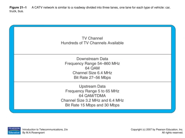
Time Warner - HFC • Fiber/Coaxial main trunks • ½” lines with amps • Taps • RG 6 to the home • Concepts of DB • -10 to +20 DB to the set
Audio • Input Level for 25 kHz Peak Deviation: • 140 mV minimum. • Manual gain adjustment with front panel control. Input Impedance: 10K Ohms, unbalanced. • Pre-emphasis: 75 m Sec. • Frequency Response: 20 Hz to 15 kHz, +1, -3 dB, referenced to 75 m Sec. • Pre-emphasis curve. 4.5 MHz • Intercarrier Stability: ± 5 kHz, 0 degrees Celsius to + 50 degrees Celsius. • Total Harmonic Distortion: 1.5% maximum. • Hum and Noise: -60 dB minimum, referenced to 25 kHz peak deviation.
RF Demodulator • An RF Demodulator tunes in TV and CATV stations to create separate audio and video signals. These devices are used to receive television signals from the over-the-air TV Broadcast band (Ch 2-69) or the Cable TV band (Ch 2-125).Most commercial grade units (like the ones shown above) have screw-on F-Type connectors for audio and video outputs. For connections using an Audio/Video Cable (composite video and analog audio), F-Type to RCA adaptors may be required.These units generally have an LED channel display and output adjustments for video and audio levels. Precision Screwdrivers should be used for these adjustments.To connect a mono modulator to a stereo device, use a Y-Jack Adapter. Strong local stations, or close proximity to a distribution amp, may require an RF Attenuator to reduce signal level.Modulator/Demodulator sets are often used on isolated Cable TV Systems to keep antenna and adjacent channel interference out of the line. UHF signals, in particular, are difficult to stop without total isolation.Standard definition devices have composite (video+audio) outputs and a combined RF input which is tuned to a specific TV channel. High definition (HDTV) and stereo versions are available, but can be quite expensive.Most are commercial grade. However, consumer grade VCR's can also be used as a TV or CATV demodulator.Note that most NTSC (Analog) broadcast TV stations are scheduled to go off the air in 2009. Consider buying ATSC (digital) units instead.
Demodulators • The HDD & HMDD Demodulators permit the delivery of digital television signals in analog format directly to a television. They also interface easily with existing analog modulators on CATV networks. These high performance digital receivers allow for the reception and demodulation of an 8VSB (Off-air SD/HD digital TV Signal) or QAM (Digital CATV) signal into a baseband NTSC video and audio output.
Holland Electronics LLC • Closed Captioning Support • Non - Volatile Memory • Agile Input • LED Channel Display