Download
1 / 25
250 likes | 395 Vues
Integrated Micropower Generator. Combustion, heat transfer, fluid flow Lead: Paul Ronney Postdoc: Craig Eastwood Graduate student: Jeongmin Ahn (experiments) Graduate student: James Kuo (modeling) University of Southern California

E N D
Integrated Micropower Generator Combustion, heat transfer, fluid flow Lead: Paul Ronney Postdoc: Craig Eastwood Graduate student: Jeongmin Ahn (experiments) Graduate student: James Kuo (modeling) University of Southern California Collaborator: Prof. Kaoru Maruta (Tohoku Univ., Sendai, Japan) (catalytic combustion modeling)
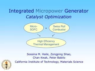
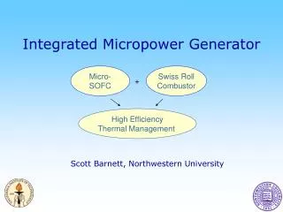
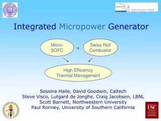
Integrated Micropower Generator Objectives • Thermal / chemical management for SCFC • Deliver proper temperature, composition, residence time to SCFC • Oxidize SCFC products Task progress • “Swiss roll” heat exchanger / combustor development • Catalytic afterburner • Micro-aspirator
Combustor development • Prior results in Swiss-roll burners show surprising effects of • Flow velocity or Reynolds number (dual limits) • Catalyst vs. non-catalyst (reversal of limits) • Lean limits richer than stoichiometric (!) (catalytic only) • Wall material
Combustor development • Limit temperatures much lower with catalyst
Combustor development • Temperature measurements confirm that catalyst can inhibit gas-phase reaction
Mesoscale experiments • Steady combustion obtained even at < 100˚C with Pt catalyst • Sharp transition to lower T at low or high fuel conc., low or high flow velocity - transition from gas-phase to surface reaction? • Can’t reach as low Re as macroscale burner! • Wall thick and has high thermal conductivity - loss mechanism?
Mesoscale experiments • Next generation mesoscale burner - ceramic rapid prototyping using colloidal inks (Prof. Jennifer Lewis, UIUC) 1.5 cm tall 2-turn alumina Swiss-roll combustor
Combustor development • 4-step chemical model (Hauptmann et al.) integrated into FLUENT (1) C3H8(3/2)C2H4 + H2 (2) C2H4 + O2 2CO + 2H2 (3) CO + (1/2)O2 CO2 (4) H2 + (1/2)O2 H2O • Typical results (V = 20 cm/s, Re = 70, lean propane-air) Temperature Heat release rate
Combustor development • Model predicts intermediates H2 and CO used in electrochemical cell H2 CO
Combustor development • Individual reactions occur at different locations within Swiss roll - possibility for in-situ reforming of C3H8 and O2 to CO and H2without a catalyst 1 2 3 4
Heat exchanger / combustor modeling • Simple quasi-1D analytical model of counterflow heat-recirculating burners developed including: (1) heat transfer; (2) chemical reaction in WSR; (3) heat loss to ambient; (4) streamwise thermal conduction along wall
Heat exchanger / combustor modeling • Results show low-velocity limit requires heat loss (H > 0) and wall heat conduction (B < ∞) • Very different from burners without heat recirculation! H = dimensionless heat loss B-1 = dimensionless wall conduction effect Da = dimensionless reaction rate
Heat exchanger / combustor modeling • High-velocity limit almost unaffected by wall heat conduction, but low-velocity limit dominated by wall conduction • Thin wall, low thermal conductivity material (ceramic vs. steel) will maximize performance
Heat exchanger / combustor modeling • Much worse performance found with conductive-tube burner
Catalytic combustion modeling • Detailed catalytic combustion model integrated into FLUENT computational fluid dynamics package • Interactions of chemical reaction, heat loss, fluid flow modeled in simple geometry at microscales • Cylindrical tube reactor, 1 mm dia. x 10 mm length • Platinum catalyst, CH4-air and CH4-O2-N2 mixtures • Effects studied • Heat loss coefficient (H) • Flow velocity or Reynolds number (2.4 - 60) • Fuel/air AND fuel/O2 ratio
Catalytic combustion modeling • “Dual-limit” behavior similar to experiments observed when heat loss is present
Catalytic combustion modeling • Surface temperature profiles show effects of heat loss at low flow velocities
Catalytic combustion modeling • Heat release inhibited by high O(s) coverage (slow O(s) desorption) at low temperatures - need Pt(s) sites for fuel adsorption / oxidation a b Heat release rates and gas-phase CH4 mole fraction Surface coverage
Catalytic combustion modeling • Computations with fuel:O2 fixed, N2 (not air) dilution • Minimum fuel concentration and flame temperatures needed to sustain combustion much lower for even slightly rich mixtures! • Typical strategy to reduce flame temperature: dilute with excess air, but slightly rich mixtures with exhaust gas dilution is a much better operating strategy! (and consistent with SCFC operation)
Catalytic combustion modeling • Behavior due to transition from O(s) coverage for lean mixtures (excess O2) to CO(s) coverage for rich mixtures (excess fuel) Lean Rich
Catalytic combustion modeling • Predictions consistent with experiments (C3H8-O2-N2) in 2D Swiss roll at similar Re • Opposite (conventional) fuel:O2 ratio effect seen in gas-phase combustion
Catalytic combustion modeling • Similar behavior at other Re
Catalytic combustion modeling • Also seen with methane - surprisingly low T
Micro-aspirator • FLUENT modeling being used to design propane/butane micro-aspirator • Goal: maximize exit pressure for given fuel/air ratio • Unlike macroscale devices, design dominated by viscous losses Propane mass fraction fields for varying inner nozzle diameters (outside dia. 2 mm)
Future plans • Build/test macroscale titanium “Swiss Roll” burner (2x lower conductivity & thermal expansion coefficient) • Test macroscale Ti Swiss Roll IMG • H2, CO, H2/CO mixtures • Hydrocarbons • Meso/microscale "Swiss Roll” • Optimized for SCFC use using FLUENT - determine the conditions required for stable 2D combustor at target operating temperature & composition • Number of turns • Wall thickness • Catalyst type & surface area • Reactant flow velocity and composition (fuel, air, exhaust gas, bypass ratio) • Build/test stand-alone Swiss roll, verify design • Build/test IMG • Design micro-aspirator