Download
1 / 11
110 likes | 239 Vues
Test Ramp for Emittance Calibration. M. Kuhn, V. Kain, F. Roncarolo, B. Dehning, A. G. Ollacarizqueta, G. Trad, J. Gras, J. Emery. Motivation: Emittance versus Intensity Loss. Results from MD I – 15/5/2012: Emittances decrease during the ramp

E N D
Test Ramp for Emittance Calibration M. Kuhn, V. Kain, F. Roncarolo, B. Dehning, A. G. Ollacarizqueta, G. Trad, J. Gras, J. Emery
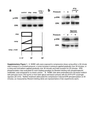
Motivation: Emittance versus Intensity Loss • Results from MD I – 15/5/2012: • Emittances decrease during the ramp • Emittance shrinkage coincides with intensity loss… • Beta functions at wires? Wire scanner calibration?
MD II (25/6/2012) Test Ramp for Emittance Calibration • Conditions: • intermediate collimator settings • 2 bunches per beam with different emittances • Cycle: RAMP - SQUEEZE - COLLISION • Wire scanner calibration • Orbit bumps at injection and flattop • K-Modulation • Flattop: point 4 • Squeeze: point 4 and triplets • Wire scans during ramp, squeeze and collision • Luminosity data
Wire Scanner Calibration • Orbit bumps at 450 GeV and 4 TeV • Going from +3mm to -3mm in 1mm steps • Wire scanner B1V, B2H and B2V similar • Calibration OK • bump versus wire scanner response fully consistent at flattop and injection • The slopes are 1 within the measurement error • No energy dependence
K-Modulation @ 4TeV • RQ6.R4 • RQ7.R4 • RQ5.L4 • RQ5.R4 Beam 1 AFTER THE SQUEEZE • RQ5.R4 • RQ5.L4 • RQ6.L4 BEFORE THE SQUEEZE AFTER THE SQUEEZE BEFORE THE SQUEEZE Beam 2 G. Trad
Before Squeeze G. Trad K-Modulation @ 4TeV Before Squeeze: After Squeeze:
K-Modulation @ 4 TeV G. Trad Noisy tune measurements specially at flattop with unsqueezed optics Preliminary results beta functions at wire scanner:
Emittance Growth • Look at emittance growth during ramp • Calculate emittance from luminosity at collision • Compare with wire scan data • Emittance determined with measured betas at injection from Rogelio’s team, at flattop and squeeze from k-modulation, interpolation in between for ramp • Error bars indicate difference between in and out wire scan
Emittance versus Intensity Loss • Results from MD II • intermediate collimator settings to not lose intensity • Still emittance shrinkage during ramp, but less pronounced than in last MD • Almost no intensity loss – not clear whether correlated to emittance decrease!
Luminosity Data • Convoluted emittance: • Used measured beta from k-modulation at β* = 0.6m for wire scanners • Single bunch intensity and bunch length • Only same bunch numbers colliding • Luminosity: β* error of 15 %, crossing angle error 15 μrad • Emittances from wire scans significantly smaller than emittances from luminosity (especially ATLAS)
Summary • Preliminary results so far… • Emittances measured by wire scanners decrease through the ramp. • …despite much reduced intensity loss • MD to • measure emittances with wires during ramp, squeeze and collisions • measure betas at wires • Re-calibrate wires • Compare to data from luminosity • …to finally know whether the normalized emittances are really smaller at flattop