Download
1 / 55
560 likes | 735 Vues
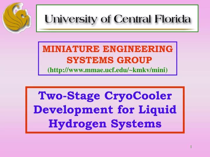
MINIATURE ENGINEERING SYSTEMS GROUP (http://www.mmae.ucf.edu/~kmkv/mini). Two-Stage CryoCooler Development for Liquid Hydrogen Systems. Miniature Engineering Systems Group Core Group of Faculty. Dr. Louis Chow Director

E N D
MINIATURE ENGINEERING SYSTEMS GROUP(http://www.mmae.ucf.edu/~kmkv/mini) Two-Stage CryoCooler Development for Liquid Hydrogen Systems
Miniature Engineering Systems GroupCore Group of Faculty Dr. Louis ChowDirector System design, spray cooling, thermal management, thermal fluids design/ experiment, thermodynamics Dr. Jay KapatCo-Director System design, design of turbo machinery, heat transfer and fluidic components, component and system testing Dr. Quinn ChenAssociate Director for Educational Programs Micro-fabrication and tribology, actuators Dr. Linan An Polymer-derived ceramic micro-fabrication Dr. Joe Cho Bio-MEMS, Magnetic MEMS, MOEMS, micro/nano fabrication, micro fluidics Dr. Neelkanth Dhere Tribological coatings, multilayer thin films, sensors Dr. Chan Ham Control, micro-satellites Dr. K.B. Sundaram Micro-fabrication, thin film, sensors, micro- and meso-scale motors and generators Dr. Abraham Wang Vibration and control, health monitoring, piezoelectric materials, shape memory alloy Dr. Tom Wu RF MEMS, miniature electromagnetic devices
Motivation and Objective • Storage of cryogenic propellants (LH2 and LOX) for extended periods have become increasingly important within NASA. There would be loss of propellants in storage tanks as well as in transfer lines both in space and ground applications due to heat leak. • The objective of this project isto design and build a cryocooler, which is capable of removing 50W of heat at liquid hydrogen temperature and thus contribute to NASA efforts on ZBO storage of cryogenic propellants and to attain extremely high hardness, extremely low coefficient of friction, and high durability at temperatures lower than 60 K for the tribological coatings to be used for this cryocooler.
Approach and Innovation • Two Stage Reverse Turbo Brayton Cycle (RTBC) CryoCooler • reliable, efficient, compact and light weight • RTBC bottom stage with He as the working fluid (immediate goal) • RTBC top stage with Ne as the working fluid • Key Enabling / Innovative Features for the bottom stage: • Compressor – Four stage centrifugal compressor with very high efficiency in its class. Design incorporates intercooling, inlet guide vanes, deswirler vanes, end wall contouring, axial diffuser at the exit integrated with after- or inter-cooler. • Motor – The motor would be a high speed three phase PMSM with a magnet integrated rotor and high frequency soft switching control system. • Recuperative heat exchanger for regeneration –Non-conventional design for reduction of axial or parasitic heat conduction, massively parallel design with micro-channels and special manifolds for ultra-high effectiveness, low pressure drop and uniform flow distribution. • Gas foil bearings – Completely hydrodynamic gas foil bearings for both radial and axial support - key in minimizing losses associated with the compressor and the motor. Tribological coatings – Extremely hard coatings of titanium nitride (TiN), bilayer coatings of TiN and molybdenum disulphide (MoS2), diamond-like-carbon (DLC) coatings, bilayer coatings of DLC/MoS2 for low values of coefficient of friction at cryogenic temperatures.
Overall Project Outline At A Glance • FY01-03 (15 months): Design: system/cycle, motor, 4-stage compressor, gas foil bearings (GFB) • Fab/testing: 1-stage compressor, coating • FY03-04 (12 months): Design: 4-stage compressor1, Rotor system, GFB2 • Fab/testing: Motor, Recuperative heat exchanger3, coating • FY04-05 (12 months): Fab/testing: 4-stage comp., other HXs, turbo-expander4, GFB w/coatings • FY05-06 (12 months): Integration and system testing • Notes: • This will be based on continued testing and optimization of the 1-stage compressor, which will be funded through an MDA/AFRL SBIR project awarded to Rini Technologies (RTI, our partner). This effort will be further helped if RTI wins another SBIR contract from NASA MFC in the Sep03 cycle. • We expect our partner Electrodynamics Associates to win an NASA GRC SBIR funds on LH2-cooled hyper-conducting motor with gas foil bearings. These funds will help in our efforts on GFB. • This effort is helped by (a) existing NASA KSC funds for a compact JT-system for in-line ZBO/pre-chilling/densification, (b) MDA/AFRL SBIR funds received by RTI on MEMS recuperative heat exchanger. This effort would be further helped if (c) RTI wins another SBIR from NASA GSFC on this topic in the Sep03 cycle. • This effort would be possible (a) through collaboration with Elliott Energy Systems (Stuart, FL) through scaling of their micro-turbines, and (b) potentially also through an SBIR from NASA KSC that RTI is competing on in the Sep03 cycle.
Efforts in Alternative Funding Sources • NASA KSC – Miniature Joule Thomson (JT) CryoCoolers for Propellant Management (funded). KSC Partners: Bill Notardonato and George Haddad. • Defense Advance Research Projects Agency (DARPA) – We have been invited to the pre-solicitation workshop on micro cryocoolers. Communicating with potential team members and planning a proposal. Also, inviting Dr. Ray Radebaugh and Dr. Marty Nisenoff (leading, world-renowned experts in cryocoolers) to UCF campus for this DARPA proposal and ongoing projects. • Harris Corporation – We have reciprocal visits for possible joint proposals to DoD. • Technology Associates, Inc. (based in Boulder, CO) – They have recently opened a branch in UCF research park in order to collaborate with us, and have provided UCF subcontracts on multiple of their DoD/NASA contracts on MEMS cryocoolers. • Rini Technologies, Inc. – partner on this project and several DoD SBIR projects on miniature cryocoolers. • Lockheed Martin Missiles and Fire Control (LMMFC) – They have provided initial funding for miniature coolers. We are currently exploring opportunities of mutual interests. Their engineers are on this project time as part-time graduate students. • Proposal for collaboration in materials research in the areas of ultra-low friction (COF<0.01) of MoS2 and carbon-based coatings with European Research Institutes from National Science Foundation is being solicited. Preparing to submit. • Proposal on Threat Control submitted to DTRA in January 2003, which included miniature cryocoolers for sensors for nuclear treaty verification. Communicating with DTRA.
Important Parameters to Measure Performance • Performance of the two stage cryocooler (with emphasis on performance of the bottom stage) – COP, weight and size. • Compressor performance – weight, size, efficiency. • Heat exchanger performance – effectiveness, size, pressure drop, and weight. • Motor performance – speed, weight, size, efficiency. • Motor control system performance – switching frequency, efficiency. • Gas foil bearings – load bearing capacity, wear during start and stop, dynamic stability. • Performance of tribological coatings – coefficient of friction, hardness, wear resistance and durability at cryogenic temperatures.
Single Stage Centrifugal Compressor • Purpose: As the four stage compressor is very difficult to be designed, fabricated and tested, and since a number of innovations are planned for size where no data is available in literature, we design, fabricate and test a single stage compressor representing one of the four stages of the proposed four stage compressor in order to obtain initial results and to generate a database for future design optimization of the four stage compressor.
Design of a Single Stage Compressor inlet guide vanes impeller blades
flow inlet Inlet guide vanes Contoured endwall flow exit Full blades and splitter blades Vaned, axial diffuser with multiple vane segments List of Innovations
Compressor Assembly Animation • This animation represents the assembly of the compressor housing containing the internal parts, coupled with the motor.
Fabrication • Rapid Prototyping • Stereo lithography models used for visualization and fit.
Fabrication • Manufacturing • Impeller cast from A356 Aluminum. • 4-axis CNC machining of diffuser and inlet guide vane.
Testing • Measurement Instrumentation • Thermocouples for temperature measurements. • Pressure transducers for pressure measurements. • Mass flow meter for flow rate measurements.
Testing • Performance Instrumentation • Digital Multimeter for power measurements. • Oscilloscope for motor speed measurements.
Sliding Mesh - Grid • Most accurate method – unsteady fluid field gives interaction between igv-rotor-stator. • More computationally demanding.
Mixing Plane-Grid • Steady state solution – losing interaction between stator and rotor. • Cost effective.
Compressor Future Work • To continue with the single stage compressor simulation and testing and to verify its design. • To integrate the single stage compressor into a four stage centrifugal helium compressor for the bottom cycle. • To design and check the fabrication feasibility of the four stage compressor.
Challenge • In the motor design, high speed will • Increase core loss in the rotor and stator. • Increase copper loss in the winding due to increased eddy current loss. • Increase bearing loss. • Increase mechanical stress in the shaft. • In the motor control, high speed will • Increase switching loss due to increased sampling frequency. • Need sensorless control due to the unavailability of the commercial position sensor at such a high speed.
PMSM Configuration • 3-phase, 2-pole • Slotless design • Rectangular Litz-wire • Laminated low loss stator core • Active length:25.4 mm • Stator outer diameter:38 mm • Winding pitch:10/15
Shaft Profile • Shaft will not fail under: • Bending stress • Shear stress • Shaft whirl • Operational speed is above the 1st critical speed. • Dynamic deflection at first critical speed : 0.361mm < 0.5mm (gap)
Shaft Centrifugal Stress Maximum Stress developed: 1210 MPa < 1700 MPa (Yield Strength of the Titanium based alloy)
Air Gap Flux Density and Torque 1.5% ripple • Low harmonics of the normal flux density. • Tangent flux density is due to large airgap. • Torque is simulated with 60.8 A phase current (back EMF: 12 V).
Major Task & Achievements in Control Design • Task: • Design of reliable and efficient 3 phase, 2 pole 200krpm motor controller with 10% speed margin. • 95% efficiency of the control electronics (without LPF). • Achievements: • Currently achieved 164 krpm. • 82 krpm for a 100 krpm sample motor, which is equivalent to 164 krpm for the 200 krpm motor. • This speed limitation is mainly resulted from the insufficient capability of the sample motor. • 80% efficiency of the control electronics including a LPF (89% without the LPF). • Tests on the efficiency, power factor, harmonics and the LPF.
PMSM Loss Motor Efficiency: Control Efficiency: Total Efficiency:
Permanent Magnet Synchronous Motor Ongoing Research & Future Work • Performing dynamic simulation of the shaft. • Fabricating and testing of a test-motor with ball bearings. • Designing of a controller for the new motor. • Enhancing the efficiency by improving the PWM and the LPF designs. • Realizing the ‘close loop control’.
Gas Foil BearingsDimensions and Present Analysis Journal bearing outer diameter = 43 mm Journal bearing inner diameter = 33 mm Inner hollow cylinder thickness = 1 mm Inner hollow cylinder axial length = 7 mm Foil axial length = 6 mm Gap between inner hollow cylinder and shaft = 5 mm Present Analysis: To determine the minimum shaft rotational speed at which the foils lift-off and the shaft is completely air borne.
Gas Foil Bearings Section under consideration for present analysis
Tribological Coatings Objective • To develop tribological coatings: • Attain extremely high hardness, extremely low coefficient of friction, and high durability at temperatures lower than 60 K. • Hard coatings at cryogenic temperature: • Coatings such as diamond-like-carbon (DLC) and nitrides of high-melting metals (e.g. TiN, ZrN) have coefficient of friction < 0.1 at room temperature but much higher values at cryogenic temperatures • A special cryogenic tribometer is required for study of friction and wear at cryogenic temperatures.
TiN by DC and MoS2 by RF Magnetron Sputtering • Good adhesion, thickness uniformity and stoichiometry of TiN and MoS2 coatings on glass and aluminum substrates verified by peel test, Dektak Profilometry and energy dispersive spectroscopy (EDS). • TiN micro hardness measurements results: HV –Vicker’s Hardness • TiN and MoS2 bilayers on Si wafer, glass and aluminum are prepared. • Expected excellent coefficient of friction (COF) and wear resistance.
TiN Coating – Aluminum and Steel Substrates • Fully reacted characteristic golden color. • All trials run at 42 rpm at RT. • Average COF for TiN/Al coating substrate = 0.143 • TiN/MoS2 for friction measurement at USF. • TiN for friction measurement at USF.
(111) (311) (006) (200) X-ray Diffraction – MoS2 and TiN • TiN and MoS2 broad peaks indicate nanocrystalline nature of sample.
Scanning Electron Microscopy - TiN and MoS2 • TiN • MoS2 • Nanocrystalline Grains (average grain size less than 100 nm) of TiN is observed. • EDS analysis have shown good stoichiometric ratio of Ti and N (Atomic Percent N : Ti = 52.91 : 47.09).
Bumps Si Sample with TiN /MoS2 film on bump Sliding Force Sliding Force TiN/MoS2 Sample TiN / MoS2 - Si Wafer Coefficient of friction tests at UCF with the assistance of Dr. Chen and his colleagues requires deposition of TiN/MoS2 coating on bumps prepared by photolithography technique and also on plain Si wafer (1 cm2) to minimize the contact area between two rubbing samples and thereby providing more accurate coefficient of friction measurements.
Friction Test – Si Wafer Average coefficient of friction for the TiN/MoS2 Bilayer coating on Si wafer with 1 N normal load was = 0.045.