Download
1 / 21
230 likes | 253 Vues
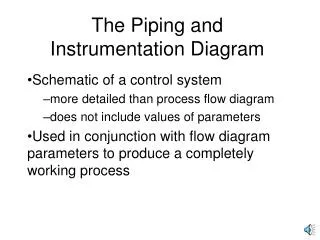
Piping and Instrumentation for Process Industries. Module II P&ID Piping and Instrumentation Diagram. P&ID. A P&ID IS: A tool for detailed engineering and commissioning A Schematic of a Process Plant A Communication Tool A Basis for Detailed Design A Guide for Construction

E N D
P&ID A P&ID IS: • A tool for detailed engineering and commissioning • A Schematic of a Process Plant • A Communication Tool • A Basis for Detailed Design • A Guide for Construction • A Guide for Operation And Maintenance • A Graphical Table of Contents to Other Engineering Documents
Piping & Instrumentation Diagram • P&ID shows all of piping including the physical sequence of branches, reducers, valves, equipment, instrumentation and control interlocks. • P&ID Symbols
P&ID A P&ID should include: • Instrumentation and designations • Mechanical equipment with names and numbers • All valves and their identifications • Process piping, sizes and identification • Miscellaneous - vents, drains, special fittings, sampling lines, reducers, and increasers. • Permanent start-up and flush lines • Flow directions • Interconnections references
P&ID A P&ID should include: Contd… • Control inputs and outputs, interlocks • Interfaces for class changes • Seismic category • Quality level • Annunciation inputs • Computer control system input • Vendor and contractor interfaces • Identification of components and subsystems delivered by others • Intended physical sequence of the equipment
P&ID A P&ID should not include: • Instrument root valves • control relays • manual switches • equipment rating or capacity • primary instrument tubing and valves • pressure temperature and flow data • elbow, tees and similar standard fittings • extensive explanatory notes
P&ID Process Utility Off sites P & ID Distribution Auxiliary Interconnectiing Packaged Unit
Notes Symbols System Process Flow Diagram Add Add P & IDs Size, Service, Line Number, Pipe Materials Specification, Tracing Type required. Sub – System and Associated System Demarcations By EPC/Vendor Others
How do we Prepare them…..? • Title Box • P & ID Numbering • Equipment Arrangement • Equipment Details • Equipment Numbering • Equipment Data • Line Numbering • Termination of Line
Line Number • There are two basic areas - These are the line number method and the line number elements. • * Methods - There are two basic line numbering methods. The first method is based on the “Purpose or Function” of the line. The second method is based on the line “Size.”* Elements - The elements that are most commonly included in a line numbering scheme are: Plant Location, Line Identity, Line Class (or Line Specification), Size, Insulation Type (when required) and Heat Tracing Type (when required).
Line Number – Methods…. • Methods – “Purpose or Function” of the line based on the line “Size.” An example of this might be a pump suction line. It might come from a Storage Tank. It travels some distance and then splits and connects to the two pumps designated for that one service or function. This is one line, it serves one purpose or function therefore it has only one line number. • Another example would be the pump discharge that leaves both of these pumps and join to form the single pipe line that runs to the next piece of equipment. This line also has one purpose or function therefore it has only one number.
Line Number – Methods…. • Methods – “Purpose or Function” of the line based on the line “Size.” • The “line size” method is, where the line number changes whenever and wherever the line size changes. • When compared to the first (purpose or function) method, the pump suction line might have five line numbers instead of one. • The pump discharge might also have five or more depending on what happens at the destination end of the line.
Line Number – Elements…. • Elements • The elements of a line number – Example 10-1021-CA1A-12”- IH -ST Where: 10 = the plant Unit or Area (mandatory) 1021 = the numeric line number (mandatory) CA1A = the line class (mandatory) 12” = the line size (mandatory) IH = Hot Insulation (only when required) (1) ST = Steam Tracing (only when required) (2)
Line Number – Elements…. • In this case the “10” refers to a physical plant area as defined by the project work breakdown structure document. Other Areas might be 20, 30, 40 or 11, 12, 13, etc. • The “1021” represents the twenty-first line in this area. All line numbers on this project will be four place numbers starting with 1000 in each area. • The “CA1A” represents the project piping material line class code for: 300# (C), Carbon Steel (A), 1/32” corrosion allowance (1) and a specific gasket type/material (A).
Line Number In addition to the line identification elements the Line List should also include some important information • The phase (liquid or gas) • The origin & destination of the line • The line pressure, both the normal operating pressure and the maximum operation (or Design) pressure • The line temperature, both the normal operating temperature and the maximum operation (or Design) temperature • An indicator code for Stress Analysis requirements • The insulation thickness (optional) • The line schedule (optional) Application : Calculation of Labour Hour Estimation
Line Identification Line Service Designation Line Numeric Pipe Size Global Pipe Spec Line Tracing Critical Line Descriptor Line Insulation
Line Continuation • Line continuations between different drawings are shown below: